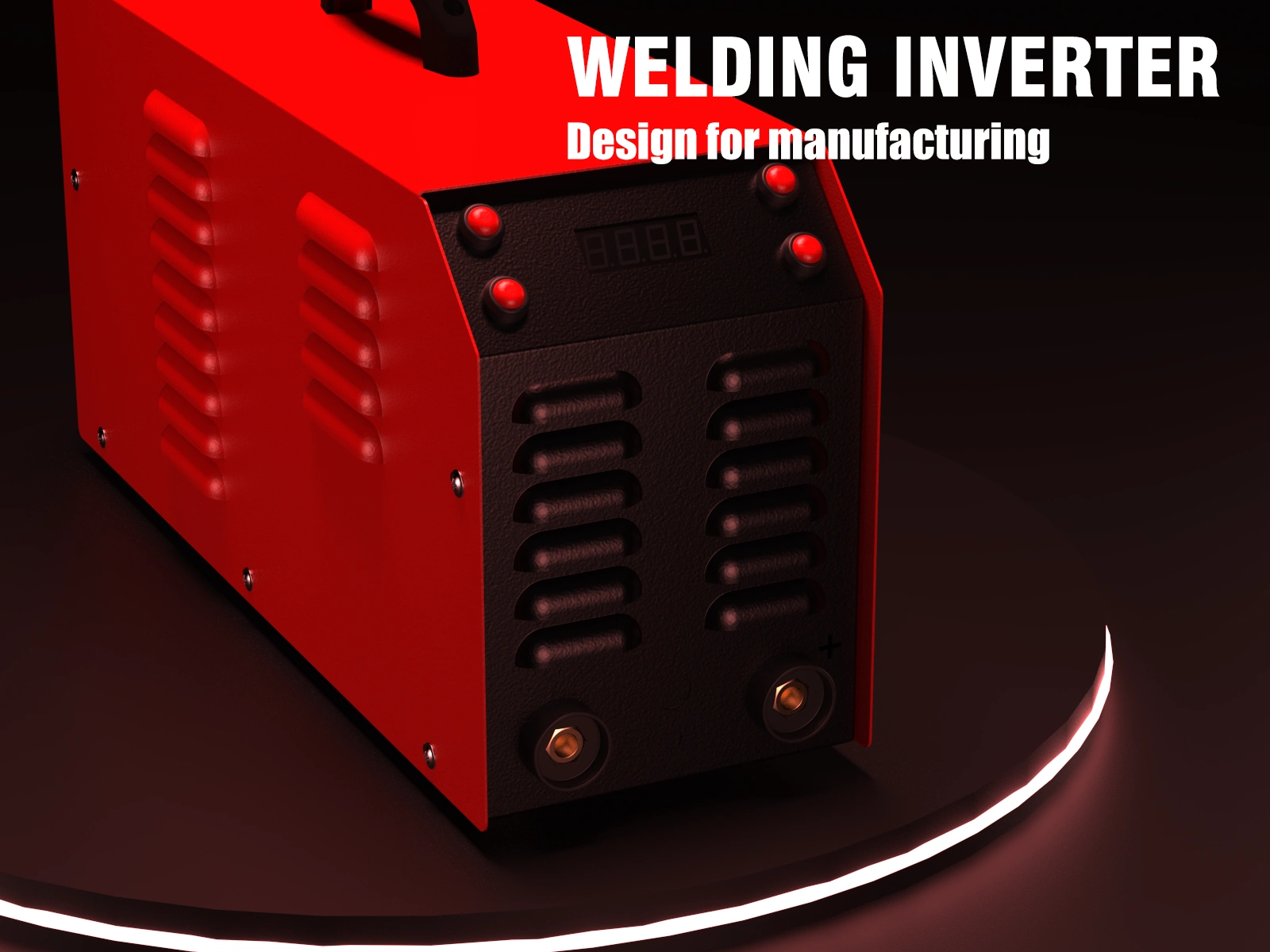
Welding invertor
Michael Komarov
Client
TENKO
Production process
Laser cutting
Sheet metal bending
Punching
Spot welding
Powder coating
Main program
PTC Creo Parametric
About the project
The inverter welding machine project was developed for a third-party customer and manufactured by TENKO, so the design had to meet not only the customer's requirements but also the manufacturer's (production-ready). The simple structure, use of simple materials, and mostly standard parts made it possible to adapt the body for mass production. The production of the body involved numerous technological processes, including laser cutting, sheet metal bending, punching with a bending machine, spot welding, and powder coating. Reducing the number of parts produced reduced production time and costs.
Project requirements
Protected housing
The housing has IP21 protection, i.e., it is protected against solid objects and vertical water drops, and the housing is also grounded.
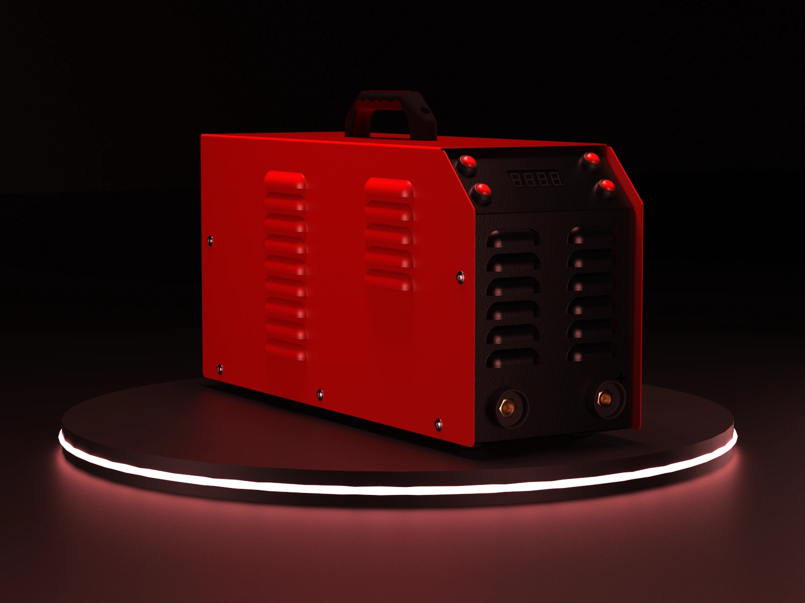
Front side
Variety of operating modes
The device itself can operate in an inert gas environment, i.e., it has connectors for a TIG torch and can also be connected to a welding wire feeder. Depending on the configuration of the device, unused openings must be plugged.
Intelligent cooling
This should be provided by the device's software and active cooling. Special openings should be designed in the housing for through-blowing of all power components of the board.
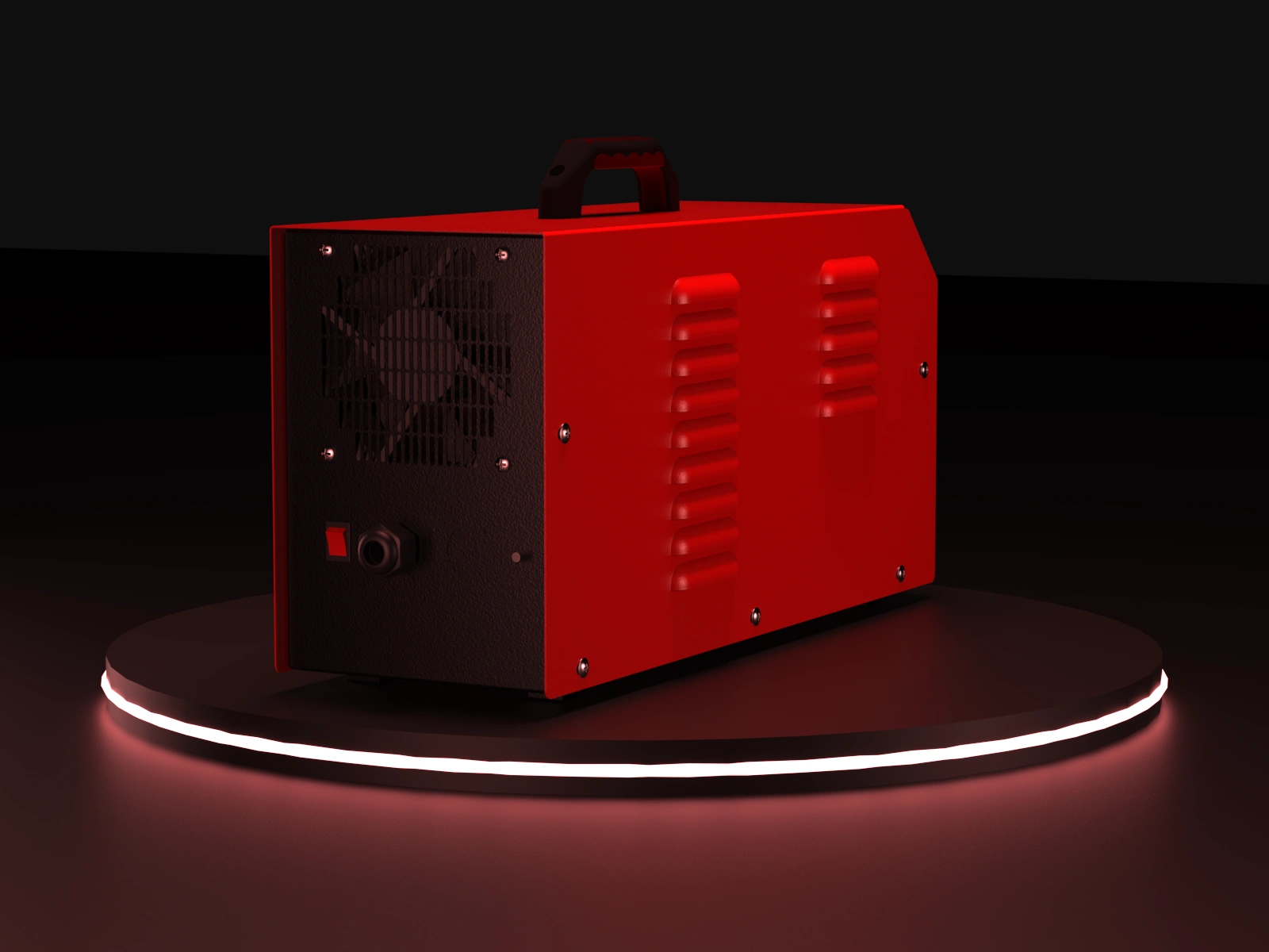
Back side
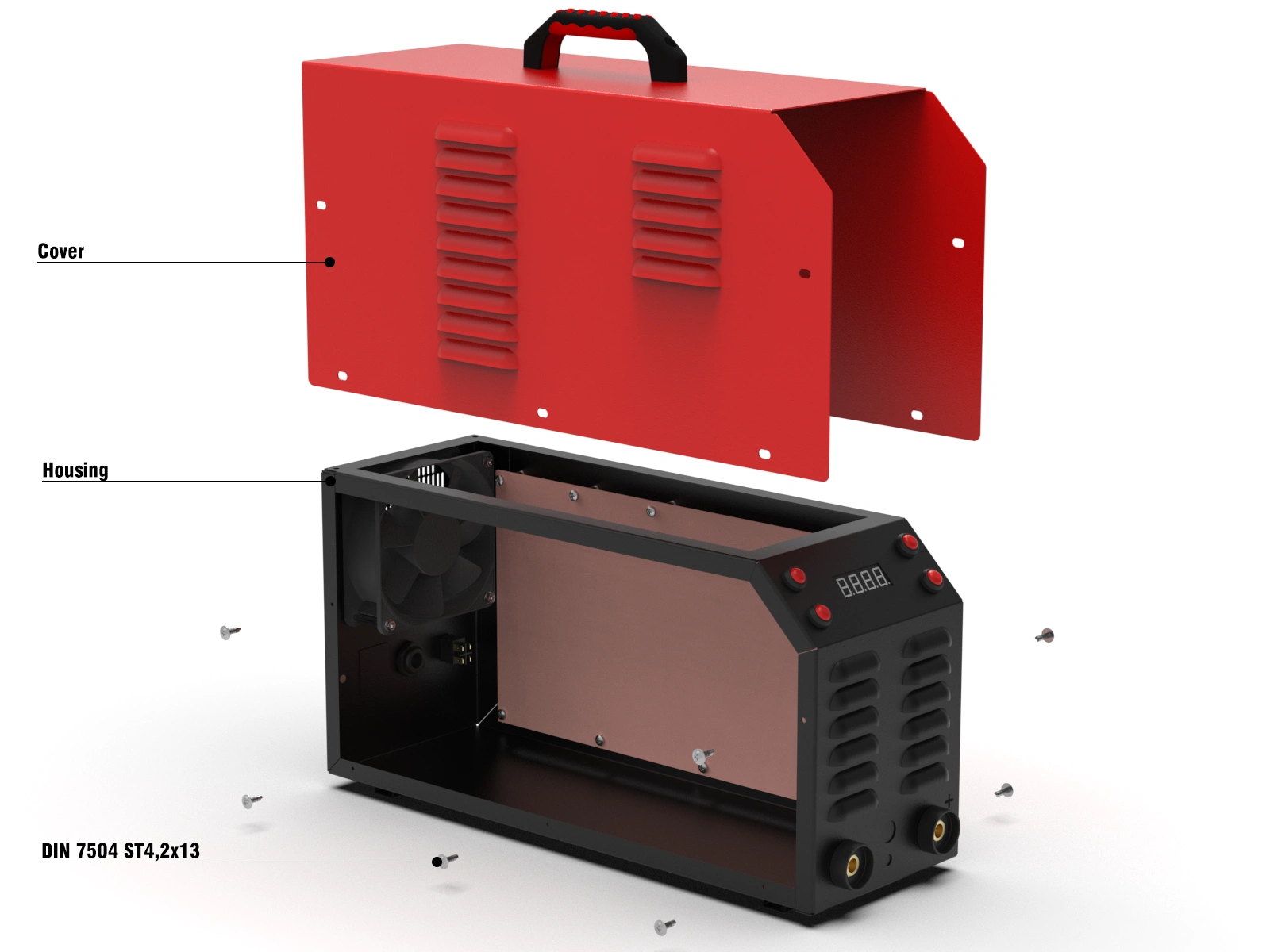
Welding inverter structure
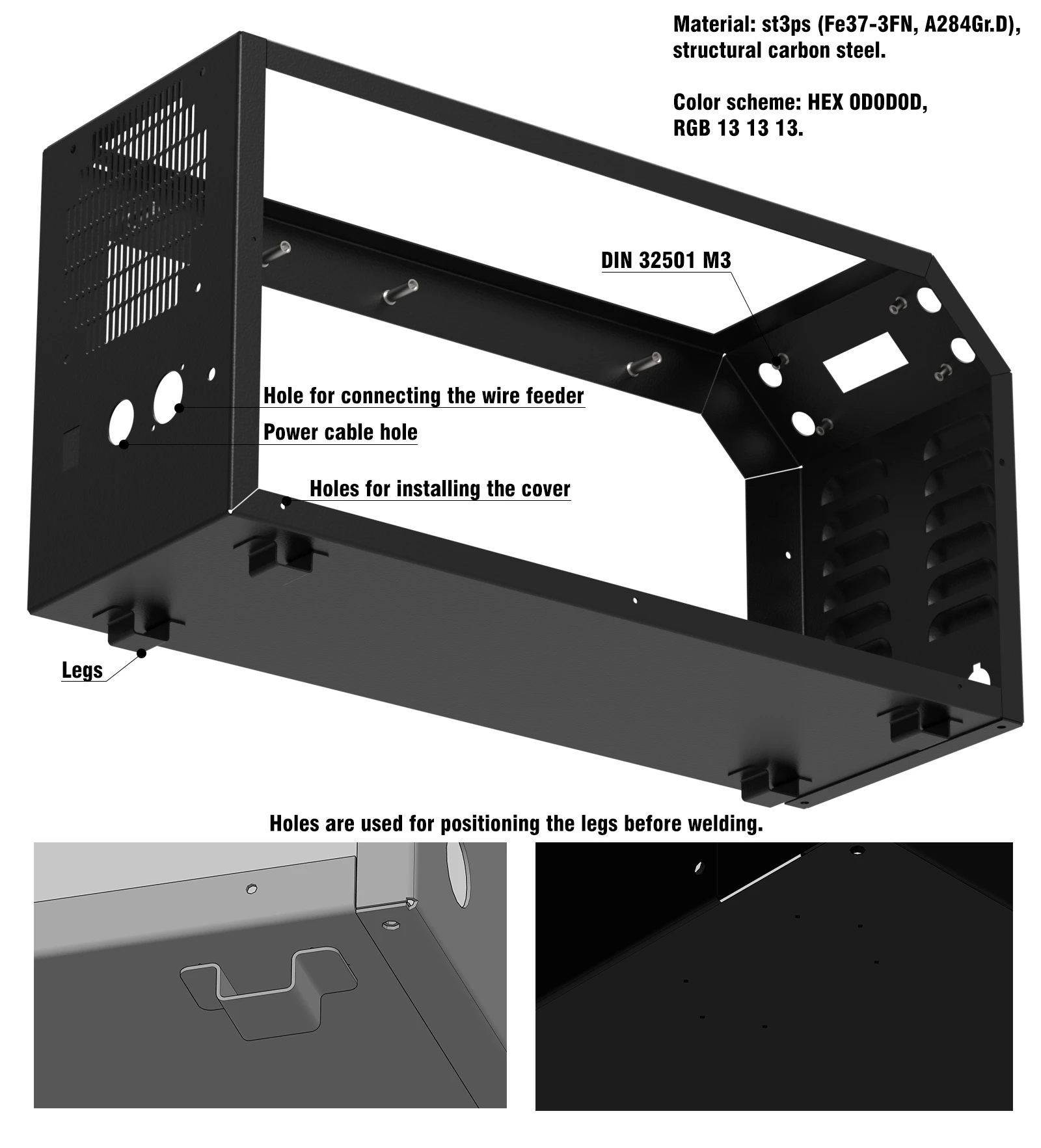
Structurally, the welding inverter consists of two parts: a cover and a housing, which are connected with self-tapping screws. However, the housing itself consists of three parts: the front part, the rear part, and the legs, which are connected by spot welding.
Welding inverter structure
To connect the front and rear parts, special holes are designed at the top and bottom, through which the parts are fastened with self-tapping screws and then welded. This is necessary for the correct positioning of both parts and to facilitate welding. Special holes are also designed for the legs at the bottom to help position the legs correctly before welding. The legs are installed in the middle between all the holes.
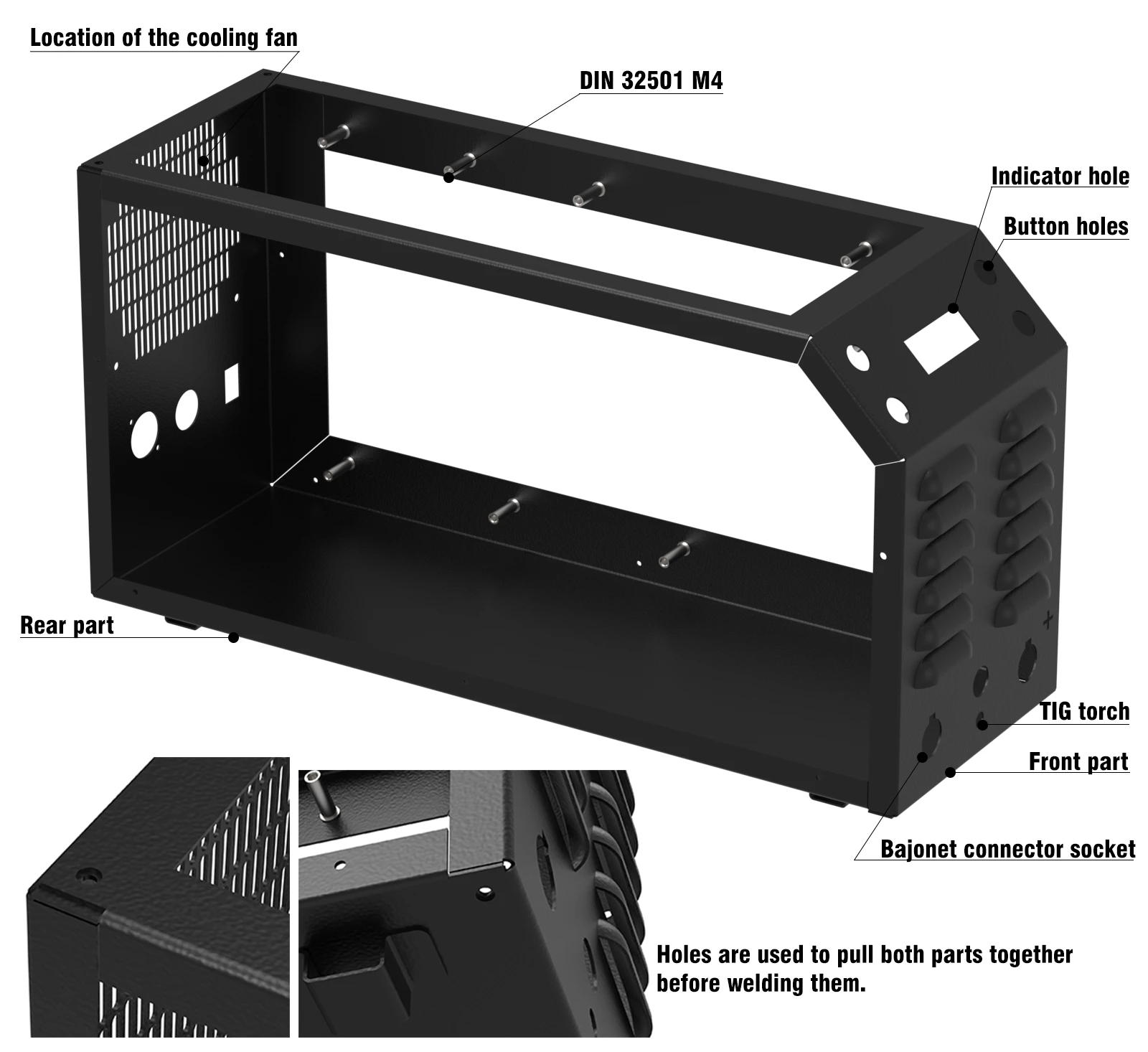
Housing structure 1
Welded threaded bushings are used to install the main power board and control board in the housing. The bushings are welded in the appropriate places on the side panel, where there are larger bends, and on the control panel. A laser in engraving mode can be used to mark the installation of the bushing.
Housing structure 2
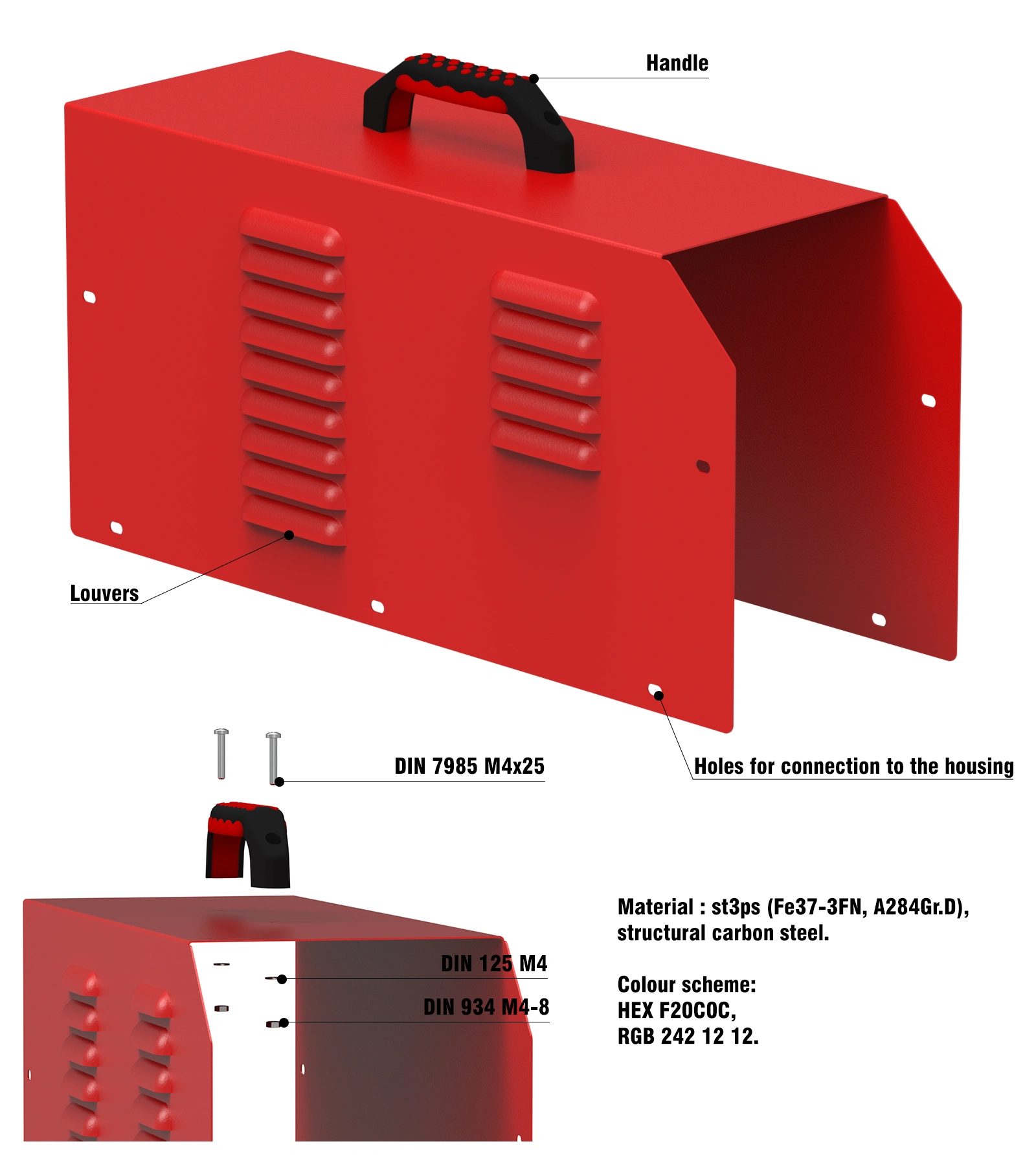
Cover structure
The cover has ventilation holes on the left side, located in areas where the electrical components are located on the board. The profile of the cover repeats the profile of the housing, and the length of the cover is slightly increased to cover all the gaps in the housing. A handle is installed on top, which is standard for the manufacturer and can be replaced with a similar one if necessary.
Cover structure
Results
As a result, we managed to make the case optimal for mass production at the TENKO factory. During the development of the case and its variations, I worked closely with the factory staff and quickly made changes to the design, so the device was put into production very quickly.
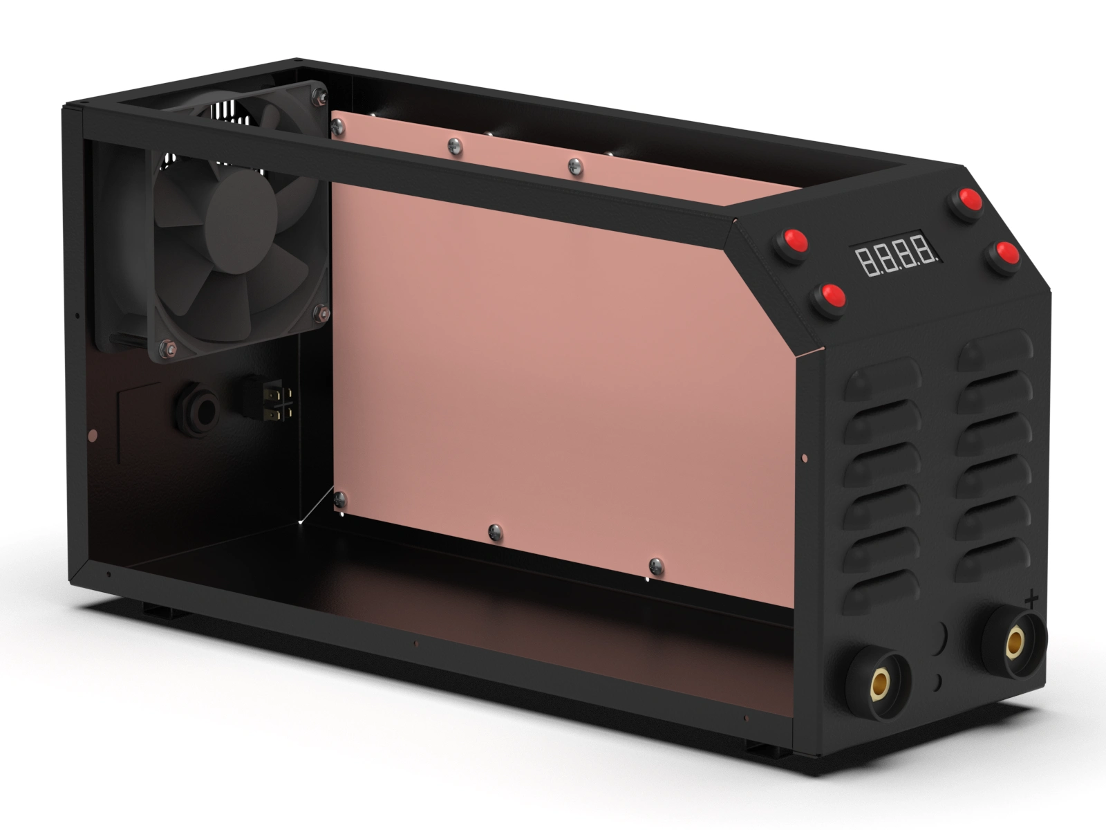
Internal structure 1
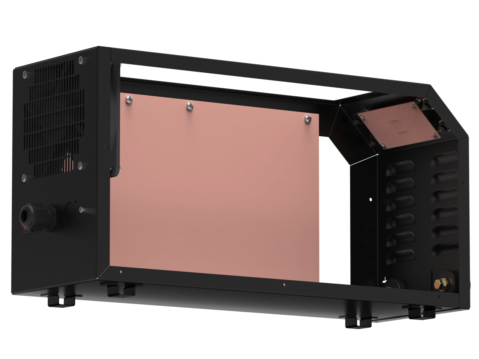
Internal structure 2
Like this project
Posted Nov 8, 2025
Creating a housing design for a welding inverter using various manufacturing processes for mass production.
Likes
3
Views
9
Timeline
Feb 15, 2018 - Mar 1, 2018