Climate Control Device Development
Michael Komarov
Client
Vladimir Kolobanov
Production process
Laser cutting
Sheet metal bending
Project members
Michael Komarov - design engineer
Vladimir Kolobanov - hardware and software developer
Ruslan Kozlachkov - sticker designer
About project
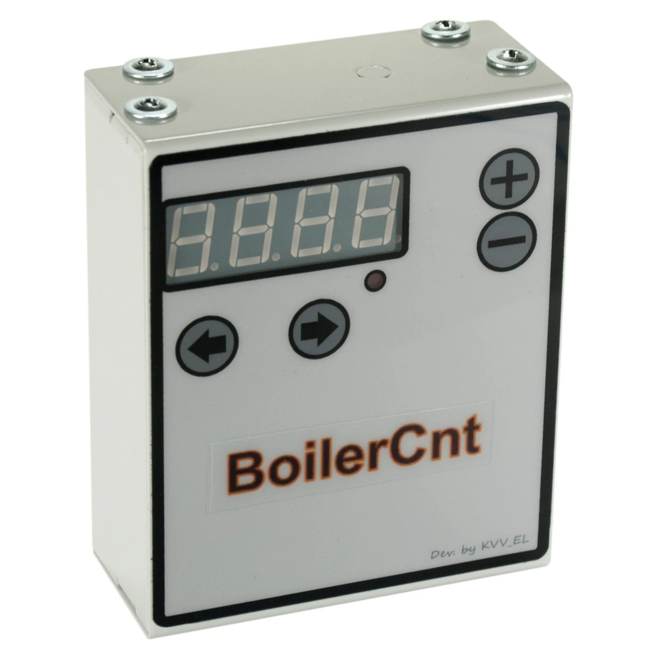
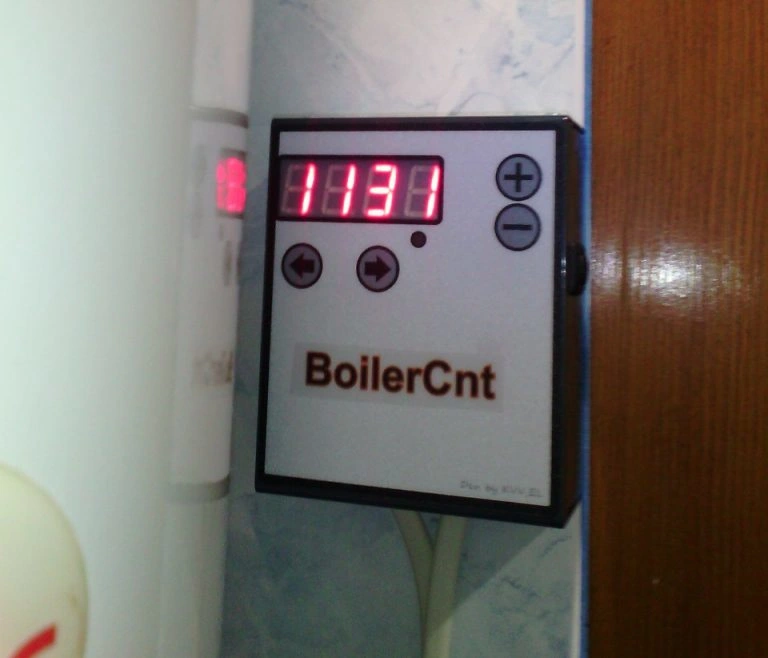
The climate control device is a device that controls the switching on and off of boilers, air conditioners, convectors, and other devices. It operates in either automatic mode (where the user enters the parameters) or manual mode (where the user controls the device directly). The climate control device operates in several modes:
user-defined time mode,
timer mode,
manual mode, in which the user turns the device on/off manually,
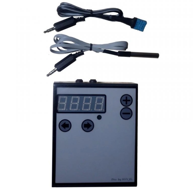
humidity and temperature sensor mode, in which the device turns off when the maximum value set by the user is reached.
The climate control device reduces the power consumption of heating elements, lowers the load on the network, and protects heating elements from overvoltage, etc.
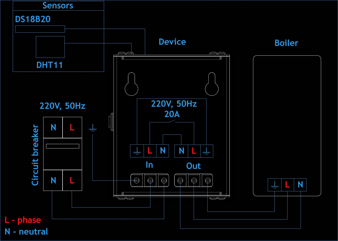
Climate control device connection diagram
Project requirements
1 Simple design
The device has a simplified design. Only two parts are manufactured, while the rest are standard parts, which helps reduce production costs and simplify assembly, thereby reducing production time. This also simplifies maintenance and component replacement.
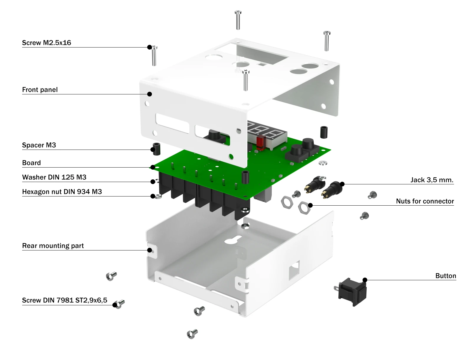
Climate control device structure
2 Easy installation
The device is mounted on the wall using the mounting holes on the back and can be removed just as quickly. The climate control device should be installed close to the boiler or other device it controls to reduce the length of the cable.
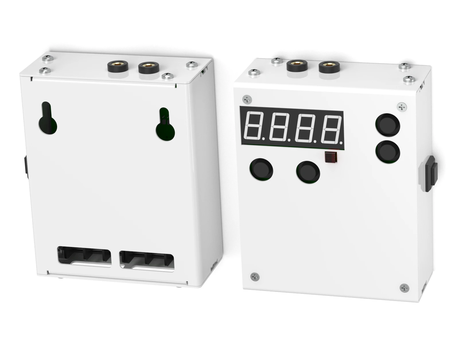
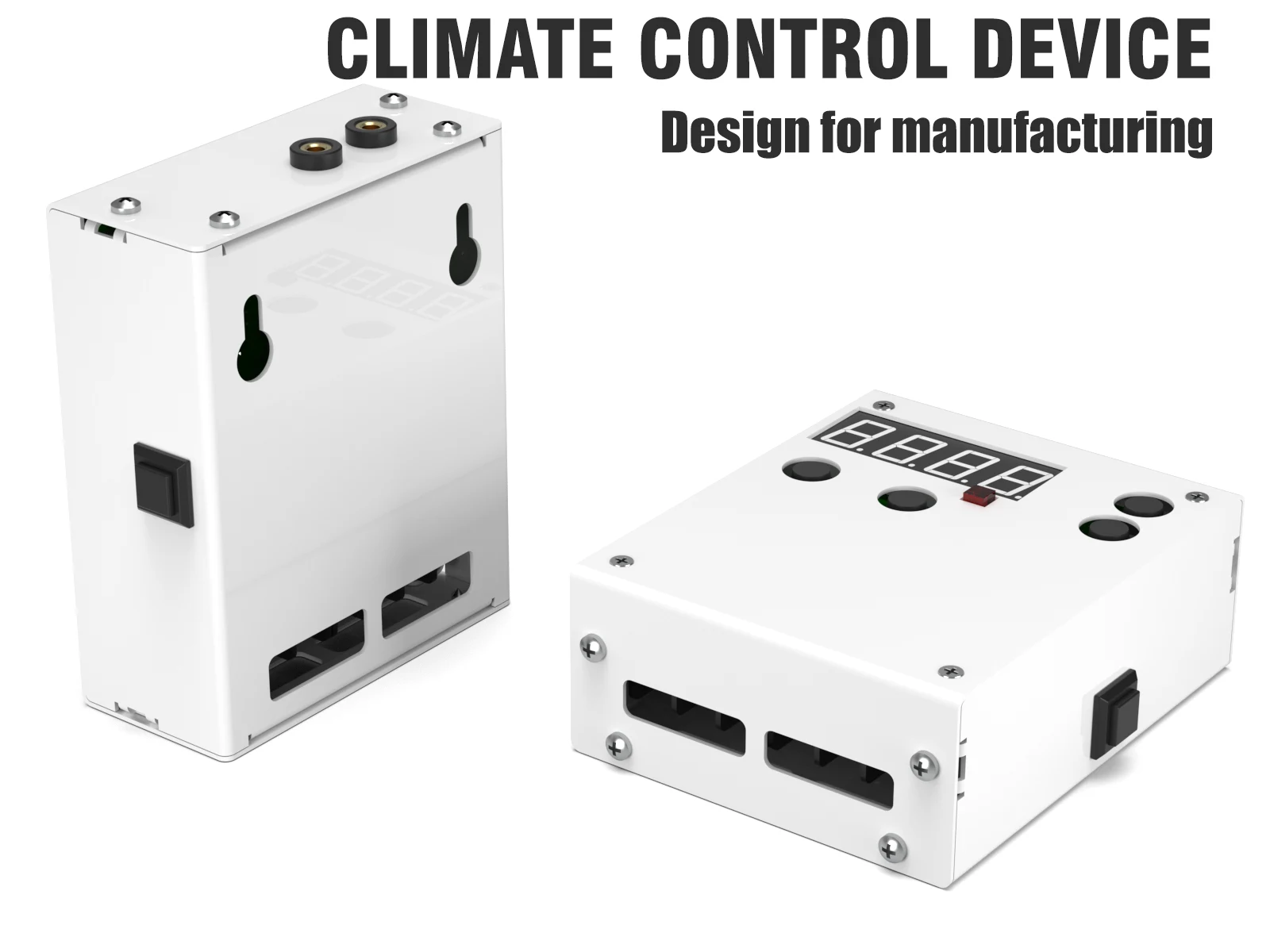
Front panel and rear wall of the climate control device
3 Flexibility
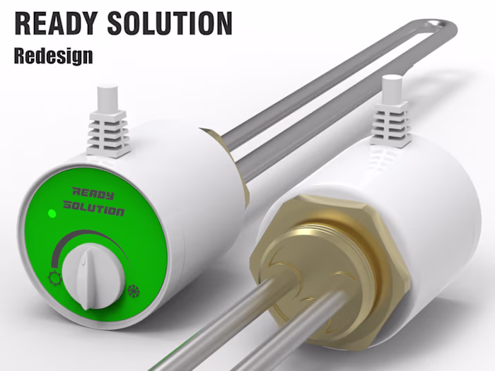
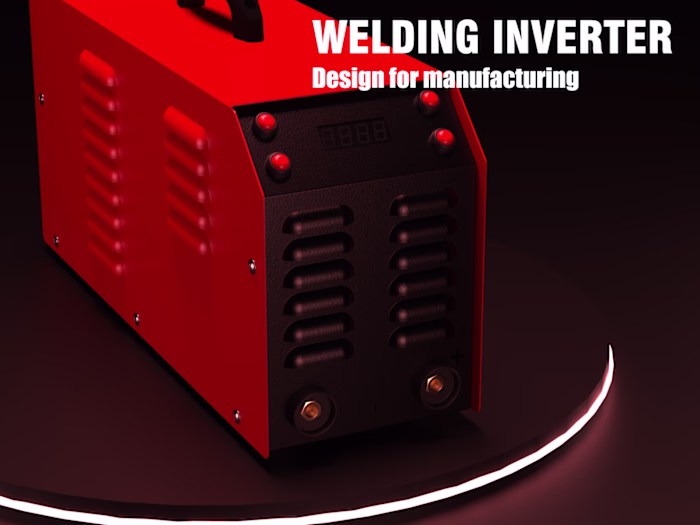
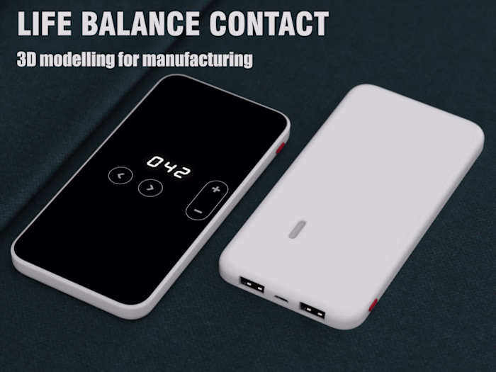
The climate control device can manage any heating device (water heater, boiler, convector, ready-made solution, etc.). This extends the life of the device and reduces electricity consumption.
Project implementation
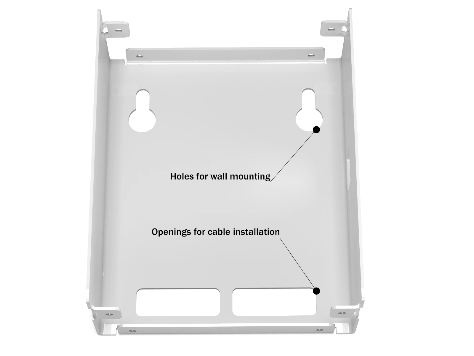
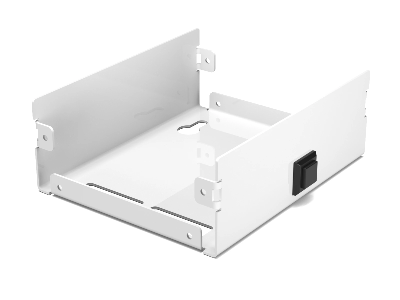
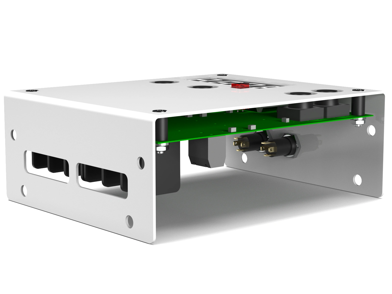
The project consists of two parts: the front panel and the rear mounting part. The rear part has mounting holes for wall mounting, which allows it to be attached using a standard 4.5 mm diameter screw dowel, as well as holes for installing cables into the board connectors. The rear part also has four bends for bending with pliers, which greatly simplifies the work for the bending machine operator.
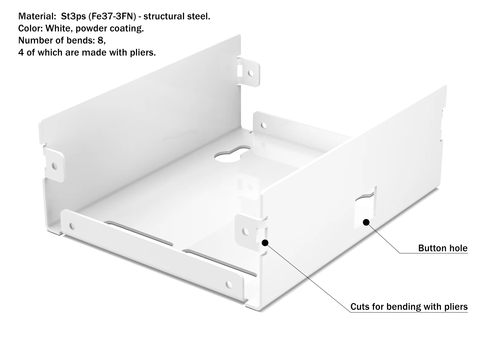
Rear part structure
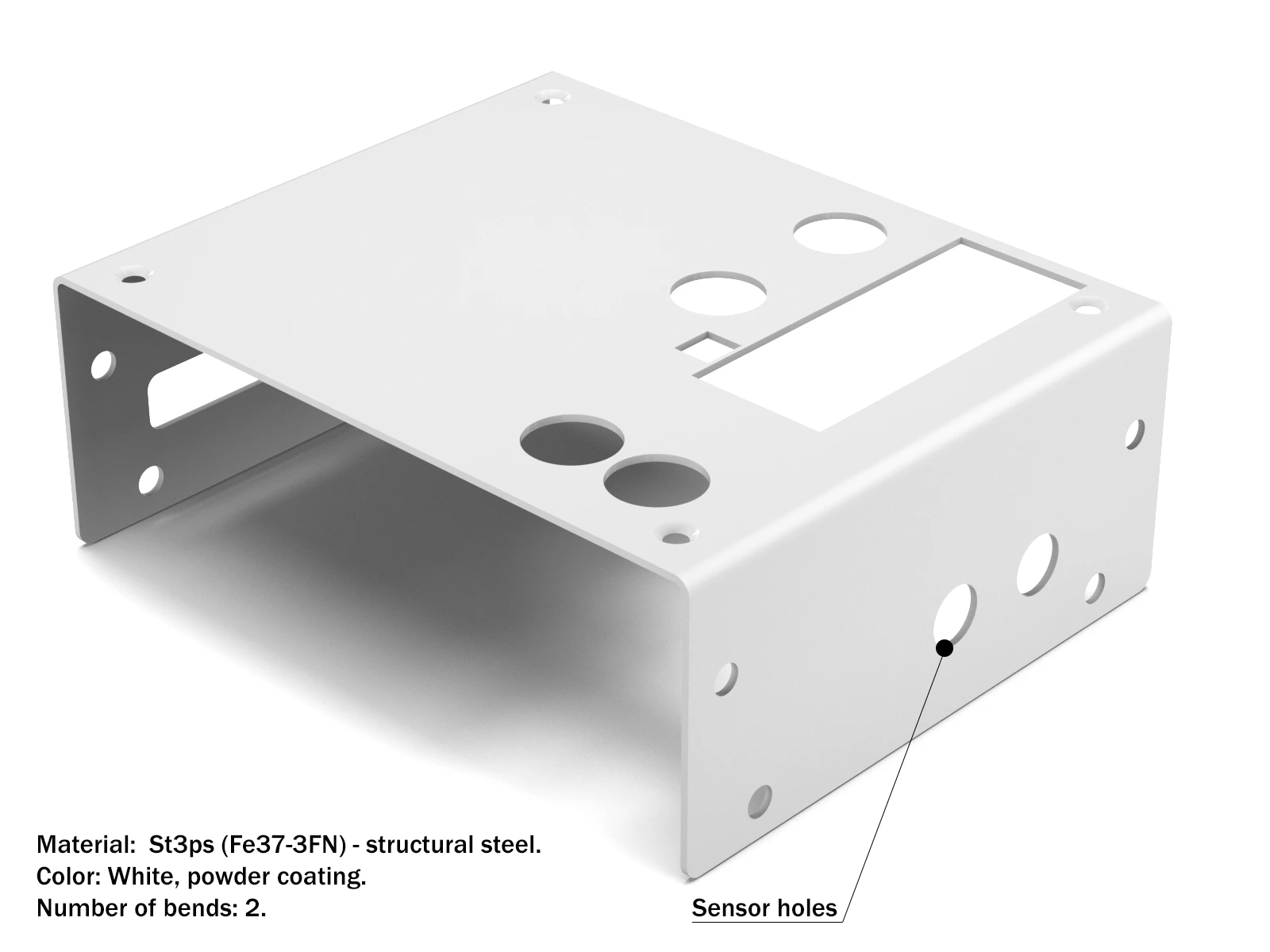
The front panel has two simple bends, and the device control board is attached to the panel. One of the design features is that there are holes in the lower part through which power cables are fed into the device, and there are special holes in the upper part for installing connectors for humidity and temperature sensors.
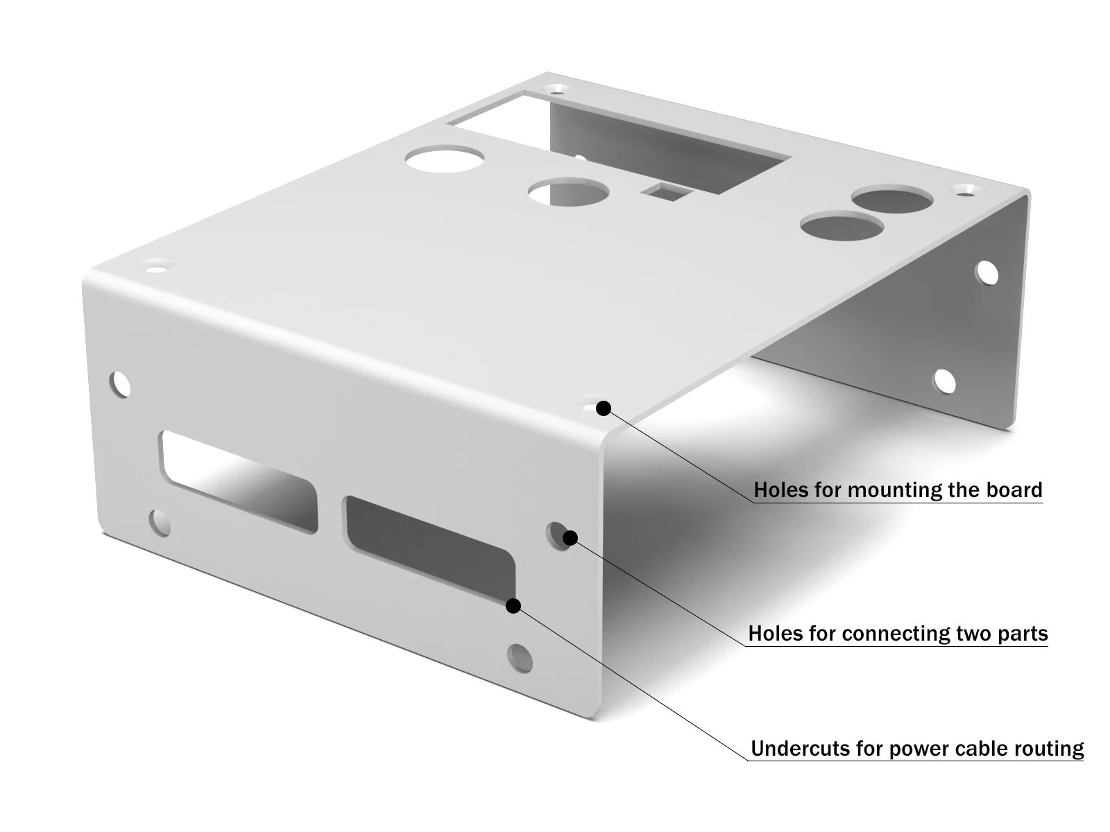
front panel structure
The device is available in three color variations:
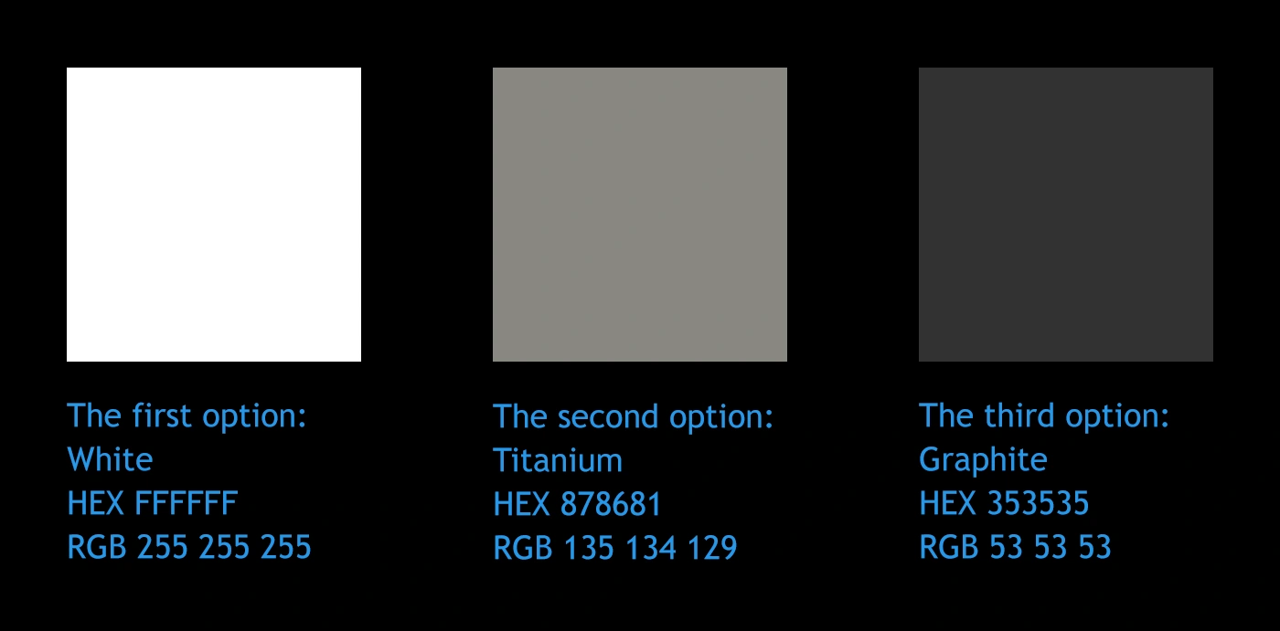
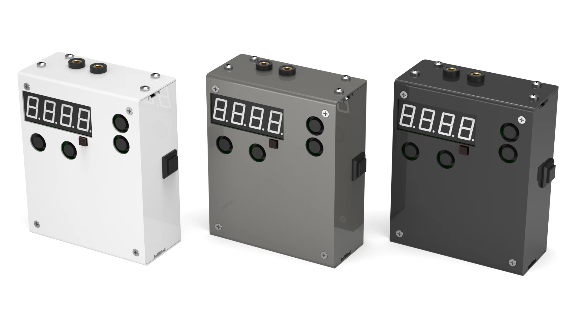
Color variations for the housing
Results
Like this project
Posted Oct 17, 2025
Developed a climate control device with simplified design and reduced power consumption.
Likes
3
Views
6
Timeline
Jan 30, 2025 - Feb 20, 2025