Engineering Explainer Video Scripts
Like this project
Posted Jun 28, 2023
I was commissioned to create two video scripts on behalf of Engineering360. I researched and wrote scripts for both Roller Bearing and AC/DC motors operation.
Bearings Explainer Video Script
Opening Narration
If it spins, there is probably a bearing behind it. These essential components ensure that wherever there is an axis of motion or rotating shaft, the rotary motion happens smoothly and with precision.
Bearings may seem simple on the surface, but they most certainly are not. Rolling elements need to be carefully designed to ensure they support the right ratios of axial or radial thrust. Bearing seals are key to any design where the bearing might encounter any type of dust or liquid ingress. And the tribological factors of bearing design alone are enough to fill university lectures.
GlobalSpec is here to help take some of the mystery away from bearing understanding. As you continue your bearing education, design or selection, remember that GlobalSpec.com is your go-to source for easy, powerful search of all your precision rotation needs.Types of Bearing
From skateboard wheels, to sliding doors to huge industrial plant machinery, bearings come in hundreds of different sizes and configurations but ultimately share one goal. To reduce the friction between moving parts and .
While there are magnetic and fluid based bearings, the most common types are mechanical and they come in two distinct forms: ball bearings and roller bearings.
Ball bearings consist of a row of hard metal balls trapped between two circular pieces of metal known as races and secured by a retainer. The inner race is free to rotate, usually connected to an output shaft while the outer race remains stationary. Ball bearings are most commonly used in high speed, low load applications, due to the small contact area of the balls to the casing.
Ball bearings come in both single and double row forms, with double row increasing the amount of load the ball bearing is able to withstand.
For applications that need to be able to withstand higher loads than even a double row ball-bearing, engineers often turn to roller bearings, which utilise cylindrical pieces of metal instead of balls, to increase the contact surface area, whilst maintaining the same rotary motion.
Both types of bearings come in different orientations, depending on the more prominent direction of the load and are usually manufactured from a hardened chrome steel alloy. This alloy can be hardened further by infusing other elements like molybdenum, for applications in extremely high stress environments, such as on aircraft parts.
Manufacturing Process
Speaking of the material - it’s really important that the rollers, balls and races are perfectly round, to ensure a smooth rotary motion in the application, and this is ensured with a rigorous and detailed manufacturing process for each.
This is the process for the balls alone:
The Balls start out as a wire or rod slug containing the proper amount of material required in the finished ball
The slugs then undergo a cold heading process to form a near net spherical shape
The balls are then filed, or tumbled to remove flash and burrs
Soft grinding is employed to produce balls of uniform size
Balls are hardened by heating them to a temperature of 1565 degrees F for 15-20 minutes, quenched in oil at 375 degrees F for 15-20 minutes, and then tempered at 340 degrees F for 2 hours.
The hardened balls undergo a finish grinding process to achieve finished size and roundness specifications
Finally, the balls undergo a lapping process to achieve final tolerances and surface finish requirements
The rollers go through a similar process, starting off as wire, but with slightly fewer steps, as cylinders are much easier to machine accurately than spheres.
Once all of the components have been through their own manufacturing process, they are measured, matched and assembled into the finished products and shipped.
Lubrication
While the rotary motion of the cylinders and spheres reduces friction, lubricant plays a critical role in maximising the lifespan of the parts, and reducing the heat even further.
Many bearings are pre-lubricated with grease by the manufacturer and this can present a couple of advantages
There is no risk of contamination with external mechanisms
Lower assembly, grease purchasing and maintenance costs
But with pre lubricated bearings:
The housing cannot be kept free from dirt, water and other contaminants
The Limited assembly space precludes the use of a grease-filled housing
Relubrication with external lubricators is not feasible
If you opt for bearings that aren't pre-lubricated, then there are a few options to consider, again depending on the application you need it for.
There's Oil, Grease, and Dry lubrication in the form of Soft Film and Soft Oil products.
While Oil has extremely advantageous lubricating properties, the many different systems all require constant attention, maintenance and still raise some possible environmental and machinery contamination concerns.
Grease is a great option for many bearing systems due to its easy application, water resistance and low maintenance, but poor cooling properties and a resistance to motion can make it a poor choice for low torque, high speed rotating machinery.
For environments where oil and grease is not feasible, engineers may turn to Dry lubrication. Often though, this is a high cost, specialist method for bearing lubrication and there are drawbacks, such as limited corrosion protection and a temporary increase in noise and vibration as small fragments of solid lubricant break free.
Outro
Bearings are a key player in many engineering operations and consumer products in the 21st Century and as you can see, there are many different factors to consider when selecting for your own applications.
We hope this video gives you a brief introduction and insight into the world of bearings and don't forget to check out all of the resources at GlobalSpec.com for even more detailed information.
Take care and we’ll see you in the next video
DC/AC Motor Operation Video Script
OPENING NARRATION
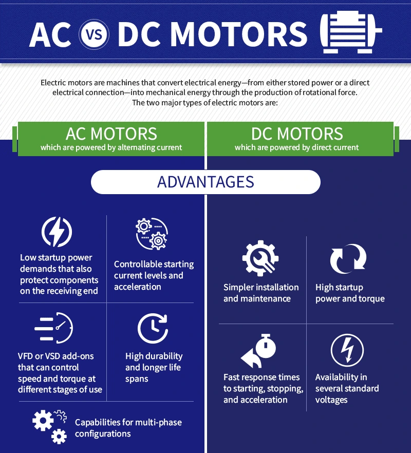
Motors are everywhere. From industrial machinery to pumps to hand tools to HVAC to automotive, our world would be a lot less capable without electric motors that provide the rotation and torque to make so many applications go.
Join Engineering360 as we take a look at some of the primary differences between DC and AC motors, as well as how to control each. And as you continue your motor education or selection, remember that GlobalSpec.com is your go-to source for easy, powerful search of all your motor and motion control needs.
Now fundamentally, In direct current, the voltage is always constant, and the electricity flows in a certain direction. In contrast, in alternating current, the voltage periodically changes from positive to negative and from negative to positive in a sine wave.
It’s this constant flow of energy in the DC supply that makes DC motors perfect candidates for jobs that require stability and precise control of speed and torque, and what makes AC motors ideal for more rugged Industrial and commercial applications.
Let's take a closer look at DC Motors.
The two main types of DC motor are Brushed and Brushless
Brushed motors get their name from the brushes that create a contact with the commutator ring on a DC Motor. When a voltage is applied across the ring, an electromagnetic field is induced around the coil on the Rotor, and causes the magnets in the Stator to repel on both sides. By constantly alternating the polarity of the magnetic field around the armature, the motor shaft is made to continuously rotate. In the majority of brushless motors, the coils are located in the Stator and the magnets in the Rotor and also rely on a 3 ‘phase’ input (hence the 3 wires always poking out the back).
Brushless motors rely on a particular arrangement of transistors (and other components) which discharge to the coils in a particular sequence to create the repulsive force for the rotation.
Brushed DC motors are often considered the workhorses of consumer goods, small appliances, and automotive applications such as windscreen wipers.
Brushless motors on the other hand, are extremely low friction, making them more suitable for operating hard drives, robots and electric vehicles.
For more specific applications that require a high level of control, there are servo and stepper motors
Servo motors allow for the precise control of position, acceleration and velocity, making use of a regular DC motor and pairing it with a sensor for position feedback. Now servo motors can be either brushed, or brushless - but the most common form is brushless, due to the nature of the applications for servo’s.
If you thought that servo motors enabled a high degree of control, then think again. Stepper motors were designed for highly attuned rotary motion, splitting up the 360 degree motion into a number of clearly defined ‘steps’. This is perfect for highly repetitive and intricate tasks in industries such as manufacturing and medicine.
So now we’ve cleared up the confusion of DC Motors, let's talk about how to control them.
Cut to the workbench where the brushed motor sits with a battery.
The brushed motor will rotate at a constant speed relative to the supply voltage of the power source, in this case X volts.
Demonstrate connecting and motor spinning, disconnecting and motor stopping
We can start the motor, stop the motor and reverse the motor by swapping the polarities of the battery.
But only having a signal at high (1) or low (0) is clearly a very limited approach to control. We need a way to get the motor between high and low: Enter PWM, the most common form of motor control. PWM or pulse width modulation is a circuit that controls the amount of power that is given to a device by cycling the on-and-off phases of a digital signal extremely quickly. Varying the width of the high (1) part of the cycle, by using a potentiometer, results in a different voltage across the device.
While we aren't going into the physics of how this works, this demonstration using the Arduino UNO and a potentiometer shows how we can adjust the speed of a DC Motor. Fortunately for us, the arduino contains a built in PWM circuitry, which means there is no need for any other external components.
Controlling the speed of a brushless motor is very similar, except it requires the use of an additional component called an ESC, or electronic speed controller, which does the job of switching the polarities of the current in a specific sequence, so as to produce the forces in the right directions for the motor to operate.
Okay so now we have the idea of speed control down, let's talk about directional control.
Ever heard of a H-Bridge? This handy little circuit is made up of four switches: two in series, and two in parallel, with the load placed in between the switches. This configuration enables the polarity of the voltage to be easily switched based on the position of a potentiometer, and therefore changing the direction of the motor.
H-bridge circuits operate the same with Brushless motors, and can even be built into ESC’s depending on the application. An RC car that requires active braking for example, would use a H-bridge to reverse the direction of the motor upon the joystick moving backwards, but a drone would not require this kind of operation.
Okay so now we have the fundamentals of DC Motor control down , its time to take a closer look at AC Motors!
The most fundamental and immediate While DC Motors run on a single phase supply, AC can run on either single or 3 phase, with the latter being then most commonly used in inudstry, due to its ability to transmit higher loads. But lets look at the two types of AC Motor:
Induction and Synchronous.
A typical AC motor contains a coil of wire and two fixed magnets surrounding a shaft. When an electric (AC) charge is applied to the coil of wire, it becomes an electromagnet, generating a magnetic field. When the stator winding is supplied with electric energy, a magnetic flux is induced from the current flow.
In AC Induction Motors, current is only supplied to the stator. The rotor of an AC induction motor is designed to short the coil in the stator, which induces another magnetic flux in the rotor. The flux in the rotor will always have a delay relative to the stator flux, but will rotate with respect to the magnetic field. This causes torque to be applied to the shaft and causes the shaft to rotate. The difference between the rotation speeds of the rotor vs. the magnetic field of the stator is called slip.
AC Synchronous motors do not depend on this induced magnetic flux in rotor and stator to operate. Instead, AC synchronous motors are constructed with magnets in the stator, which produce a rotating magnetic field. In a synchronous motor, current is supplied to the rotor, which also has a magnetic field, typically produced by a permanent magnet. Rotation is caused by interaction of the stator's magnetic field with the rotor's magnetic field.
Unlike an induction motor, the rotor in a synchronous motor will rotate with no lag or time delay. They are called synchronous because at steady state, the rotating speed of the rotor is equal to the speed of the rotating magnetic field in the stator. The rotation of the rotor is synchronized with the supply frequency.
The stator requires three-phase power for all three phases in the stator. Synchronous motors have an advantage over single-phase induction motors – with synchronous motors, the starting direction can be selected.
Control
While there are a number of way to control AC Motors, the most common way is to adjust the frequency of the supply through an AC Controller, or AC Drive. The most common configuration of an AC Motor looks like this:

There are a few key ways to achieve control though variations of this particular circuit :
1. variable voltage inversion (VVI)
2. pulse-width-modulation (PWM)
3. flux vector drives.
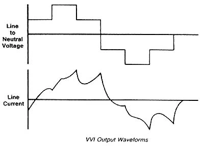
In Variable voltage inversion, the AC frequency of the power source is rectified to a DC current, which is then increased and decreased in discrete steps to imitate a sine wave (or how a true AC current oscillates). This way, operators can regulate these steps to effectively change the motor speed, and these are commonly referred to as six-step inverters

As in DC Motor control, another method is to use PWM, a concept that we touched on before.
Flux vector drives require microprocessor-based controllers, software, and oftentimes encoded sensors to precisely tune the independent currents. These drives typically provide speed accuracy of up to 0.3%, and while more impressive than the other two options, they generally come at a heavier installation and operational cost.
SUMMARY OF AC VS DC Motors

Motors, both AC and DC play a critical role in many modern day applications and the proper installation and maintenance of this equipment is essential to keep operations running smooth.
While we have only scratched the surface of motors and motor control in this video, make sure you go and check out the GlobalSpec.com resource platform for more detailed information, as well as a comprehensive list of suppliers for all of your motor needs.
We hope you enjoyed the video and see you in the next one!


