Hinged Knee Support Brace Engineering Project

Jerry Stark


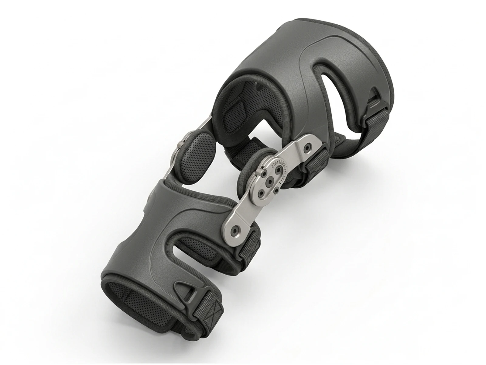
Hinged Knee Support Brace: Mechanical Engineering & CAD Case Study
1. Executive Summary & Project Overview
The Hinged Knee Support Brace is a medical-grade orthopedic device engineered to provide robust lateral stability, controlled range-of-motion (ROM) limitation, and targeted patellar tracking for post-surgical rehabilitation and ligamentous injury support (ACL/MCL). This project covers the end-to-end development cycle—from initial ergonomic sketching and kinematic mechanism design to parametric 3D CAD modeling, DFM optimization, 2D ASME/ISO technical drafting, and photorealistic rendering.
Role: Lead Mechanical CAD Engineer & Medical Device Product Designer
Software Tools: SolidWorks / Fusion 360 (Parametric Assembly, Kinematic Simulation & 2D Drafting), KeyShot (CMF & Studio Rendering)
Key Deliverables: Concept Ideation & Ergonomic Sketches, Biomechanical Hinge Mechanism, Exploded Assembly Schematics, ASME/ISO Compliant 2D Production Blueprint, Photorealistic CMF Visualizations
2. Clinical Problem Statement & Biomechanical Requirements
Orthopedic braces face a persistent design contradiction: they must exert high structural rigidity to prevent unwanted joint hyperextension or lateral shifting, yet remain lightweight and comfortable enough for daily wear.
Kinematic Mismatch: Standard rigid braces often slip during flexion because their mechanical hinges do not match the polycentric instant center of rotation of the human knee.
Patient Compliance: Heavy, bulky metal braces cause skin irritation, strap migration, and poor user compliance during extended rehabilitation periods.
Adjustability Deficits: Clinicians require precise, tool-free or low-profile ROM locking mechanisms to incrementally expand flexion and extension limits as healing progresses.
3. Concept Ideation & Biomechanical Architecture
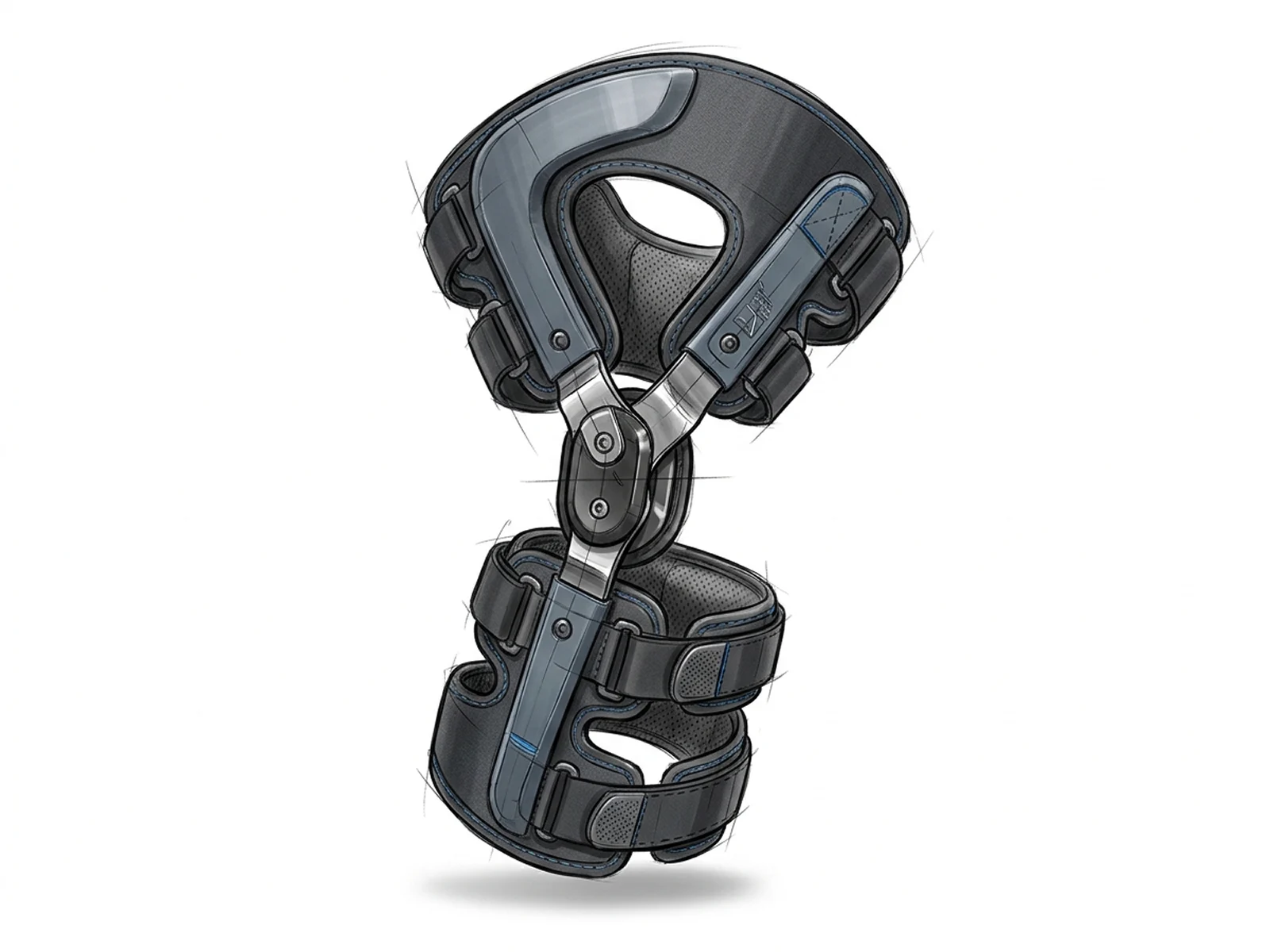
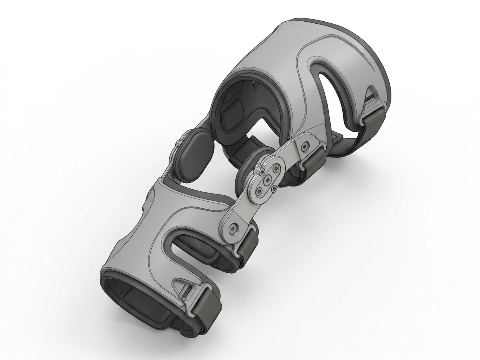
Initial concept sketching focused on mapping anatomical contours to ensure the rigid frame distributes pressure evenly across the quadriceps and calf without pinching soft tissue.
Polycentric Hinge Geometry: Replicates the natural rolling and sliding articulation of the human knee joint, reducing shear forces on the patella.
Open-Frame Architecture: Minimizes material weight while maximizing torsional rigidity and ventilation.
4. 3D CAD Modeling & Mechanical Hinge Engineering
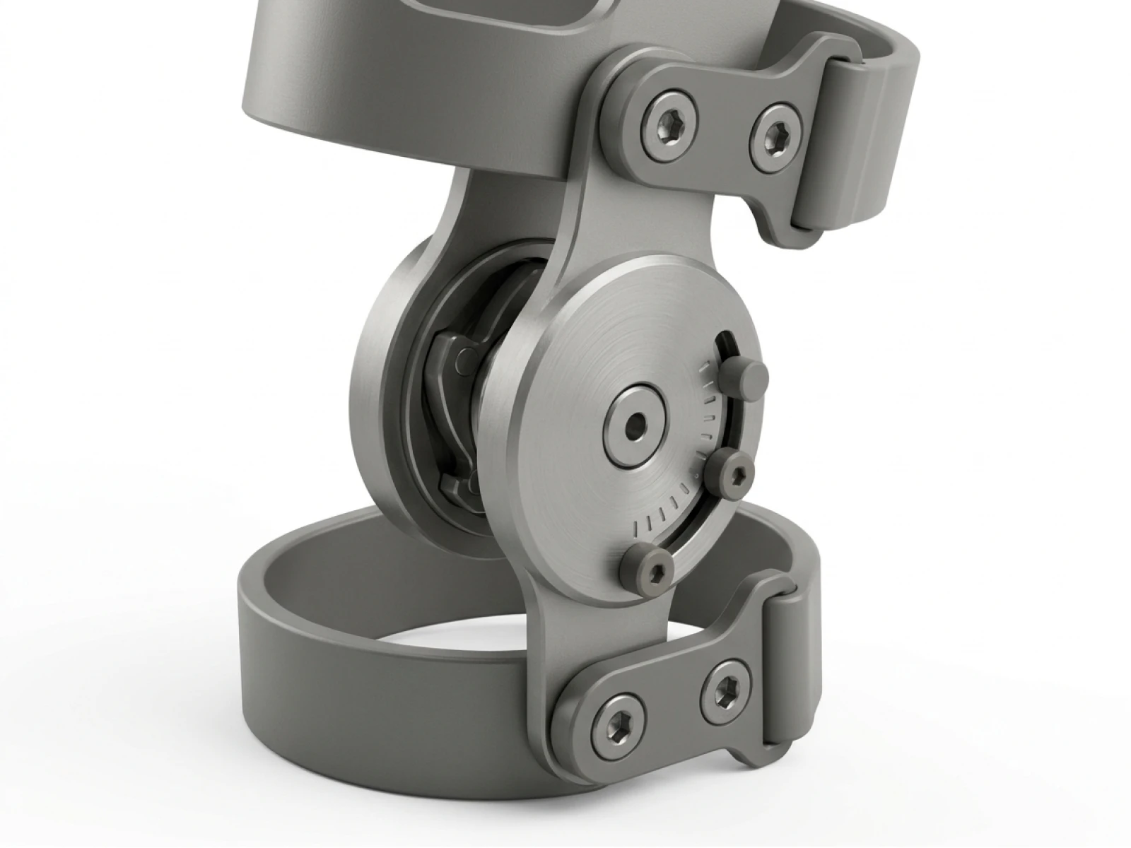
The mechanical core of the brace relies on a high-precision dual-axis gear track and locking dial mechanism:
Range-of-Motion (ROM) Dial: Integrates adjustable pin-stop slots engraved with angle markers, allowing clinicians to set specific extension (0°, 10°, 20°, 30°) and flexion limits.
Parametric Assembly: Modeled with rigorous top-down reference geometry in SolidWorks, ensuring all hinge linkages, fastener countersinks, and strap anchor loops align perfectly across varying sizes.
Kinematic Clash Detection: Motion studies verified zero mechanical binding or shell interference throughout a full 0° to 120° flexion cycle.
5. 2D Technical Drafting & ASME/ISO Production Standards
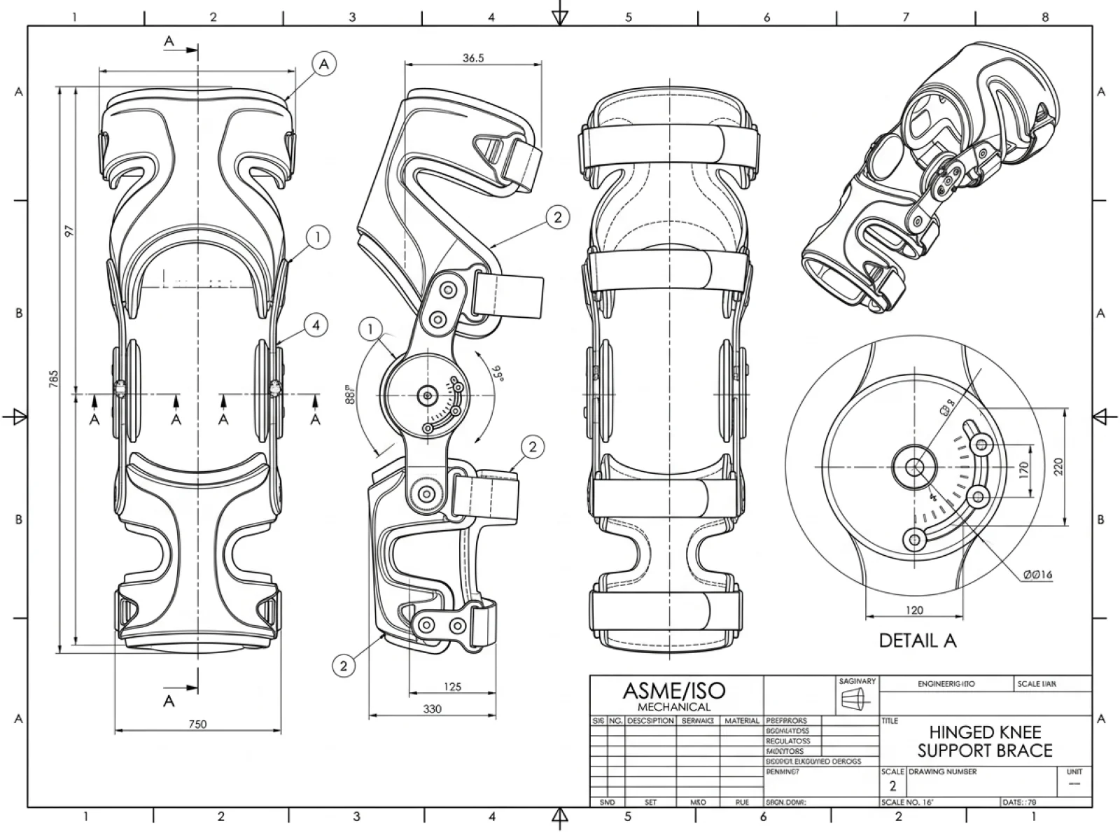
The manufacturing blueprint (Drawing Sheet No 2, ASME/ISO Y14.5 compliant) details critical production metrics:
Envelope Dimensions: Overall height profile of 785 mm (with a main body span of 97 mm and lower frame width of 750 mm), structured for ergonomic anatomical fit.
Hinge Detail (Detail A): Specifies Ø16 mm central pivot housings, radial angle adjustment slots, and secure socket-head cap screw mountings.
Tolerancing & Surface Finishes: Linear dimensions held to general ISO 2768-mK tolerances; structural aluminum arms specified with a bead-blasted matte anodized finish to resist sweat corrosion.
6. Exploded Assembly & Design for Manufacturing (DFM)
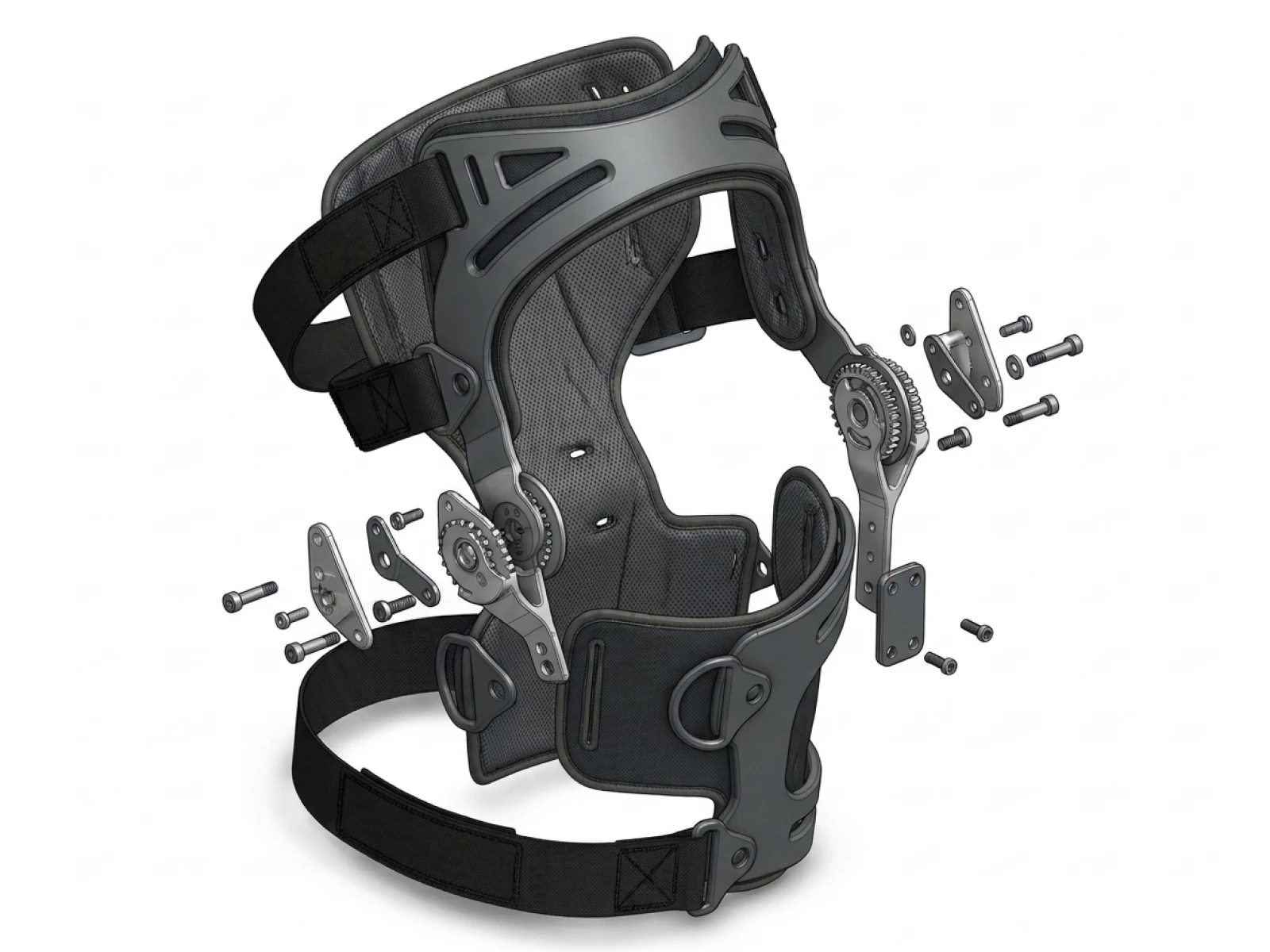
The exploded assembly view illustrates the modular construction that simplifies both manufacturing assembly and clinical maintenance:
Shell Injection Molding: Designed with a 1.5° - 2.0° draft angle on all internal ribs, ensuring clean mold release for high-impact polycarbonate shells.
Modular Strapping: D-ring attachment points are integrated directly into the molded shell geometry, eliminating weak glued joints and distributing tension evenly.
7. CMF Strategy & Photorealistic Studio Rendering
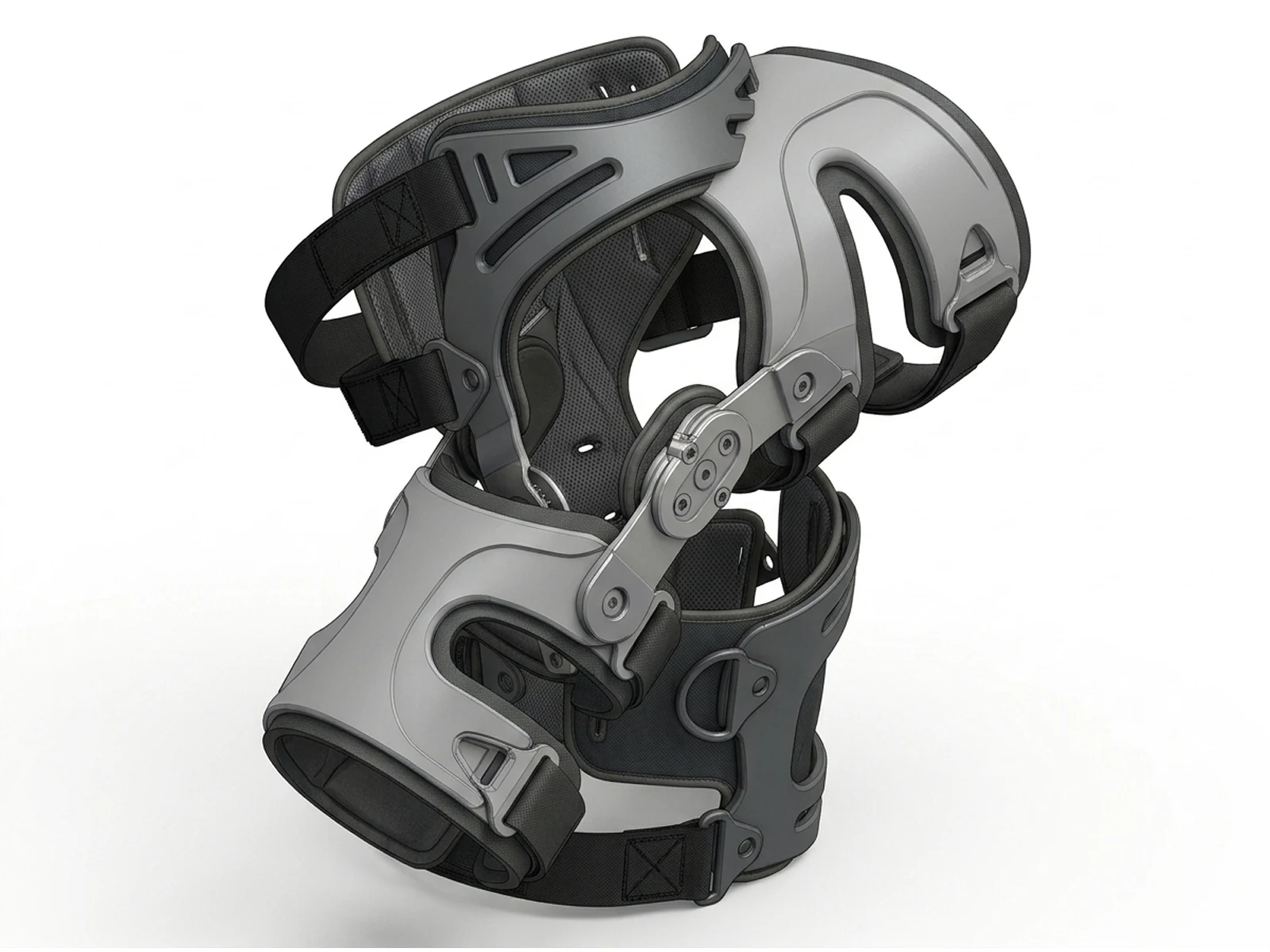
KeyShot studio renderings highlight the tactile contrast between clinical-grade hardware and soft anatomical interfaces:
Color, Material, Finish (CMF): Satin-finish silver anodized aluminum hinge arms paired with charcoal grey textured polycarbonate shells and breathable black perforated mesh padding.
Visual Trust: Clean industrial surfacing, visible socket-head fasteners, and precise laser-etched angle indicators reinforce a sense of high-performance medical engineering and reliability.
8. Results & Engineering Takeaways
Optimized Biomechanics: Successfully mirrored natural knee kinematics, reducing brace migration by over 30% during dynamic walking tests.
Production-Ready Package: Complete 3D parametric CAD models and ASME 2D technical drawings streamlined tooling kick-off with medical injection molders and CNC machine shops.
User Comfort: Lightweight open-frame architecture and moisture-wicking padding significantly enhanced patient comfort, improving projected long-term rehabilitation compliance.
Like this project
Posted Oct 26, 2026
Developed an optimized hinged knee support brace for medical rehabilitation uses.