Engineering: How to build a mediagua (2010)
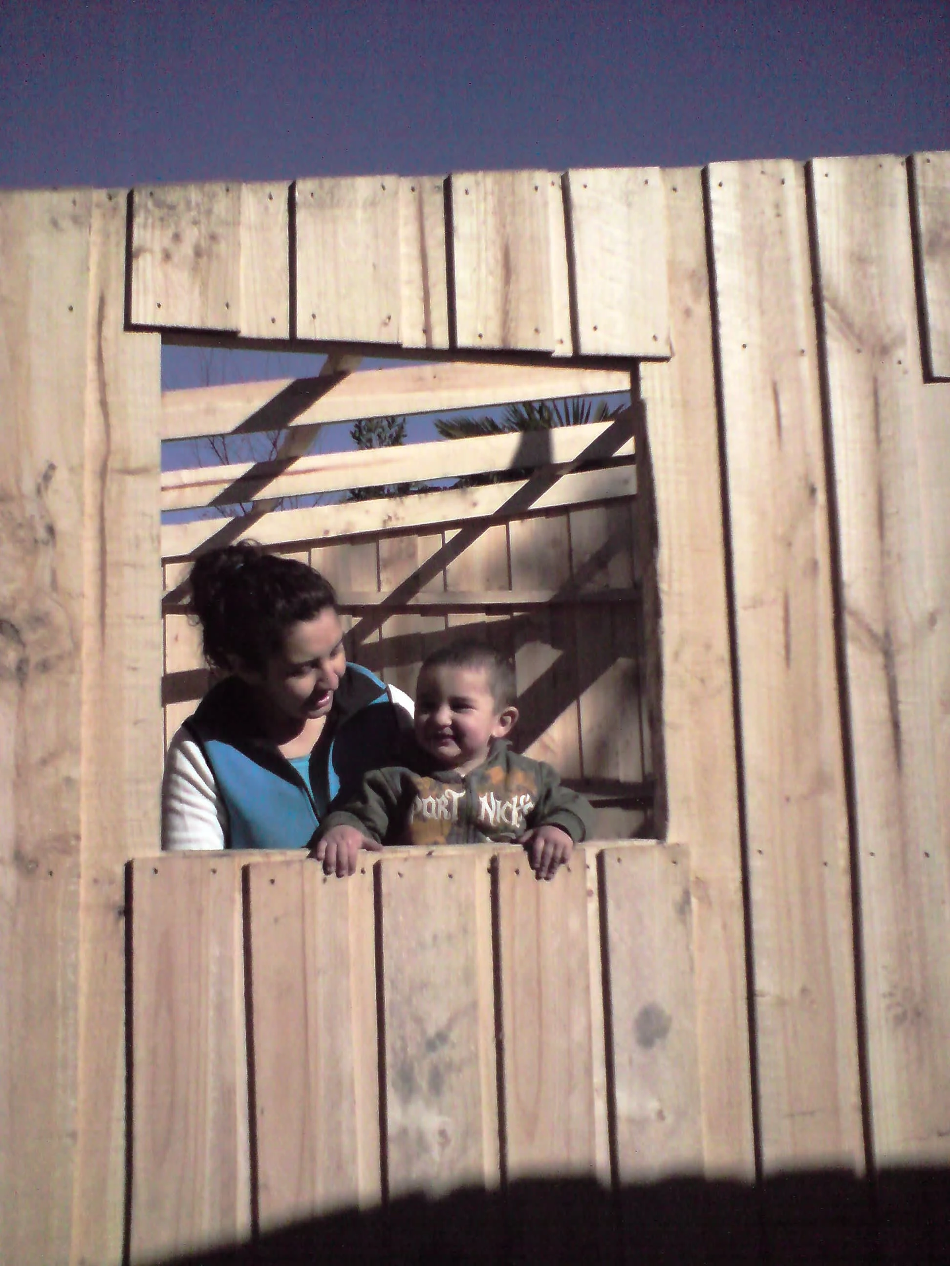
Putting a roof over Emilio and his mother Lorena in Linares, Chile, May 2010. Photo by Ben Angel.
On February 27, 2010, an 8.8-magnitude earthquake struck central Chile. Ranking as the eighth most powerful earthquake in the world, the event left thousands without homes in its wake. In response to this situation, the Chilean government asked the non-governmental organization “Un Techo Para Chile” to raise 20,000 prefabricated temporary homes called “mediaguas”.
The mediagua, sometimes translated to “shack” in English, was designed in Chile by a group of university students in 1997 under the auspices of Jesuit Father Felipe Berrios. Over the past 13 years, the group, which later became “Un Techo Para Chile” (and “Un Techo Para Mi Pais” covering much of Latin America), set a goal of replacing all makeshift homes and tents in Chilean homeless encampments with mediaguas in time for the 2010 Chilean bicentennial year.
At 18.3 square meters in area (with 6.1 meters in length and 3 meters in width), the mediagua is intended to house a family of four for a temporary period. Construction involves the field installation of a 15-pile or 17-pile foundation, the assembly in place of 8 panels (2 floor panels, 2 back panels, 2 side panels, and 2 front panels, the latter of which contain windows and a door). The roof consists of a master beam, 6 secondary beams, and 6-8 rafters, which are overlaid with tar paper and 8 sheets of zinc.
Although the design for assembly is simple, the plans are often regarded by new builders as being less than complete as a set of building instructions. For that reason, this manual was devised as a set of instructions that could be used for later construction efforts. Suggested times are included to help teams gauge their progress.
How to build a mediagua – quick guide
Before beginning
Review the site hazards and bring along appropriate PPE.
Find out how many piles will be required (if no floor beams, then 17 piles are needed instead of 15).
Review weather conditions and the period of civil twilight (to determine when it will be too dark to work without artificial light).
Site selection (15-30 minutes)
Ask the new owner about the dominant direction of the wind at the site (recommend orientation so that the mediagua has minimum exposure to the wind).
Ensure the site won’t interfere with permanent reconstruction.
Select a prepared location or prepare it so that there is a maximum elevation difference of 30 cm from one end to the other.
Master Pile (1 hour)
Set the master pile in the lowest corner, and not the highest corner, as this will ensure that all piles will be at a depth needed to remain stable. The pile should be buried to 50 cm depth (plus or minus 10 cm; all piles should be more than 80-90 cm in height).
Place a layer of gravel below all piles to prevent settlement.
The master pile sets the height for all the other piles and is one of two that sets the horizontal location of the other piles.
Other Piles (3 hours)
Set the second pile, preferably on the nearest corner 3 meters away. Ensure with the hose that it is level, and then backfill. Check to see that it is in the correct position (3 meters external-to-external) before locating all other piles. (This is the other pile that sets the horizontal locations for all the remaining piles.)
Locate the other piles using two tape measures simultaneously from known points (some may be found by determining halfway points between known piles, but use triangles to find the locations for most of the piles).
Always check the elevation of the top of each pile before backfilling. After backfilling, double check the location of the pile and the level. If within 8 cm of the desired horizontal position, tilt the pile. If larger than that, pull the pile up and try again. If 1-5 cm above vertical position, hammer the pile downward. If too low, pull up and place more gravel underneath.
Checking Piles (1-2 hours)
Are the external piles set 3 meters exterior-to-exterior along the width side, and 6.1 meters exterior-to-exterior along the length side?
Are the inner piles in the correct positions (305 cm for the center row, 152 cm for the quarter rows, middle piles at 122 and 182 cm if in a 17-pile configuration, and the center column at 150 cm, all ON CENTER)? Do these positions match the floors that are to be installed?
Are all the piles at the same height?
If everything checks out, install the floor beams (if available), along the exteriors on the outside rows, and in the center on the interior row.
Floor (30 minutes)
Use caution as the floors are the heaviest panels.
Floors should rest on the exterior of the piles, or the floor beams (if used).
Hammer in the floor if it is set correctly.
Walls (1-2 hours)
Stage wall panels in the center of the floor in reverse order of pieces to be raised.
Raise each “U” (the shape created by the back, side, and front when put together) one at a time.
First, raise the side and back panels so that they are on the edge of the floor. Nail these two together. DO NOT NAIL INTO THE FLOOR (yet).
Raise the front and connect to the side panel. DO NOT NAIL TO THE FLOOR (yet).
Raise the second “U”.
Connect both “U” shapes in the center so that the panel edges are together. Ends or center may be off the floor as a result.
Now nail to the floor in an order based on whether the center or the sides are raised from the floor (if center, nail from one side toward the center, pushing the bottom beam of the panel downward; if sides, nail from the center outward, pushing the bottom beam of the panel downwards). No gap should exist between the floor and the bottom beams of the panels.
Main beam (30 minutes)
Ensure that the rafters have been cut to 2.9 meters in length so that there are 6-8 “chongo”-pieces ready for use in making spacers (“tacos”).
Cut the spacers to 20-22 cm length and nail together.
Cut the two best 1×4 lumber to 3 meters in length.
Nail into the center beams of the front and back at 11 cm down from the top-edge beams (or one 1×4 beam downward from the top-edge structural piece).
Insert the “tacos” so that the secondary beams can connect rectilinearly to both the sides and the master beam (ideally at 74-69-69-74 cm spacing).
Include additional supports below the main beams to add strength to this element (this piece holds up the entire roof).
Secondary beams (30 minutes)
Cut the pieces at 313 and 314 cm in length (1 cm difference in the diagonal cut).
Possibly trace the connection between the secondary beam and the tacos, to cut out and fit exactly into place (note: each beam must be kept track of if so fitted, as the tacos will be slightly different from each other).
Nail into place (one set of secondary beams should be on one side of the “tacos“, and the other set on the other side).
Rafters (30 minutes)
Set the rafters at 10-105-90 cm from the top for a 6-rafter configuration, or 10-73-72-72 for an 8-rafter configuration (depending on available rafters).
Nail the rafters into the top beams of the front and back.
Nail the rafters into the secondary beams.
Terminal Elements (2 hours)
Cut out the bottom beam in the doorway.
Ensure that the window shutters and the door fit into their spaces.
If the terminal element fits very tightly into its place, chisel out the places where the hinges are to fit (10 cm from the edge for the window shutters, 15 cm from the edge for the door with other hinges spaced evenly between). If loosely, then mark out where the hinges are to be installed with a pen, and don’t chisel out (if a spacer is required to block out excessive gaps, install).
If not using power tools to screw the hinge in, nail in a pilot hole before screwing in the hinge. Screw the hinges first onto the terminal element before screwing the hinge onto the frame. There should be a minimum of three hinges for the door, and two for the window shutters (nail one of the windows shut if the organizers have given only two hinges for the door).
Ensure the terminal element opens easily.
Install bolts and ensure that they work easily.
Tar paper and zinc roofing (2-3 hours)
If no flashing is used, bend roof elements using spare lumber so that the 40 cm end piece bends downward 5 cm.
If using tacks instead of staples, punch each tack through a small piece of cardboard so that they don’t rip through the tarpaper when nailed into place.
Place in one row of tar paper, then the zinc roofing over top. Nail only the outside of the zinc (with the inside left loose so that the second row of tar paper can be overlapped and tacked onto the rafters). Avoid bending the roofing near the connection with the outside edge.
Tack in the second row of tar paper, and nail in the second row of zinc roofing.
Follow through with the third and fourth rows of tar paper and zinc.
If flashing is used, install the flashing to the uppermost rafters so that it covers the gap between the two sides of the zinc roofing.
Opening ceremony for the new owners
Clean up the floor and nearby grounds, neatly stacking excess materials for the new owner.
Collect all gear.
Conduct a ceremony following whatever tradition the new owner or the volunteer workers wish to use (ribbon cutting, etc.).
Ensure that the new owners are happy with the results.
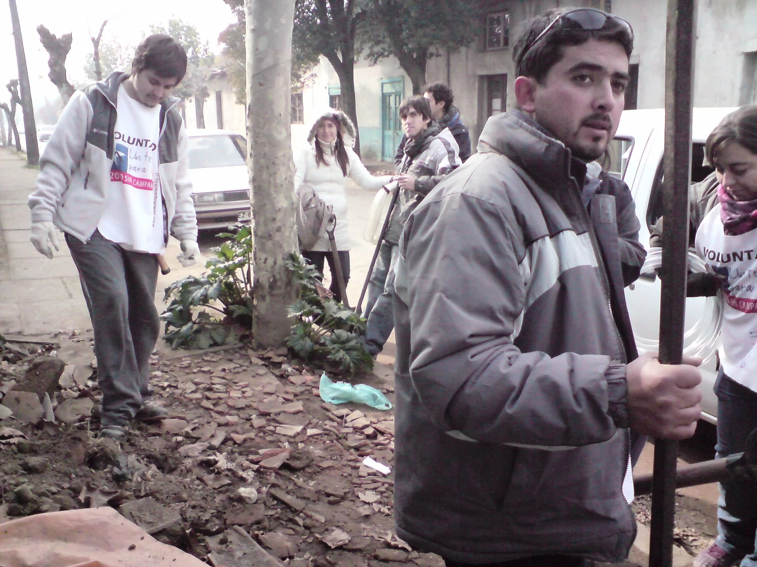
Volunteer team arriving at their worksite in Linares, May 2010. Photo by Ben Angel.
Details: Start of work
There are three issues that a team leader should address with the construction organizers before setting out to work:
What are the hazards to be concerned about? (These range from animal and insect hazards to weather, to hazardous plants, etc.)
How many piles will be used in the foundation? (This will usually be decided based on the availability of foundation beam material, or 2×4 lumber, and the quality of the soil in the area of the construction.)
What will be the civil twilight period for the weekend? (This is the period when it is bright enough to safely work without artificial light, usually about 30 minutes on either side of when the sun is above the horizon.)
These should be addressed before leaving home by organizers, or where possible, researched at the volunteer’s own initiative.
An area where volunteers can have the greatest impact on the success of the project is safety. The prevailing Chilean attitude seen in the efforts following the February 27 earthquake has been to rely on individual “common sense,” an archaic concept that many constructors in North America and Europe are moving away from. Counting on individuals to “use common sense” typically doesn’t work, particularly in a learning environment (such as building a mediagua) where a lot of the activities may be completely new to volunteers.
Instead of relying on individual “common sense” alone, many constructors in the northern hemisphere are adopting a safety attitude called “Behavior Based Safety” or BBS. In its simplest form, it sets the responsibility for the safety of everyone on all persons at the site. If an unsafe condition is observed, each person should be empowered to stop the work so that the condition can be assessed, and if needed, corrected. In a BBS-based environment, team leaders should stress this empowerment at the start of each work shift, setting as a first goal that everyone returns home with as many working parts on them as they came out with, and a second goal of completing the mediagua.
Personal protective equipment or PPE (safety glasses and gloves in particular, not to mention hard hats, footwear, and the proper equipment for working at height), is often eschewed as being unnecessary. First aid kits should be at all sites but are rarely provided by organizers or team leaders. Until a concerted effort is made by organizers to concentrate on safety (this is likely to happen only after enough severe injuries are sustained – such is human nature), volunteers should bring their own PPE and first-aid kits.
Usually, volunteer groups will have a slow start on the first morning of construction. The concept of setting the working day to the period of civil twilight is still a new one to most volunteer groups in Latin America, so teams can expect to lose 3-5 hours of daylight as members are finalized and sites assigned. Once teams have been assembled, they should waste no time collecting tools and getting to their work locations (if they are not dependent on transportation to reach their site). Of course, they should encourage organizers to get an early start, if possible.
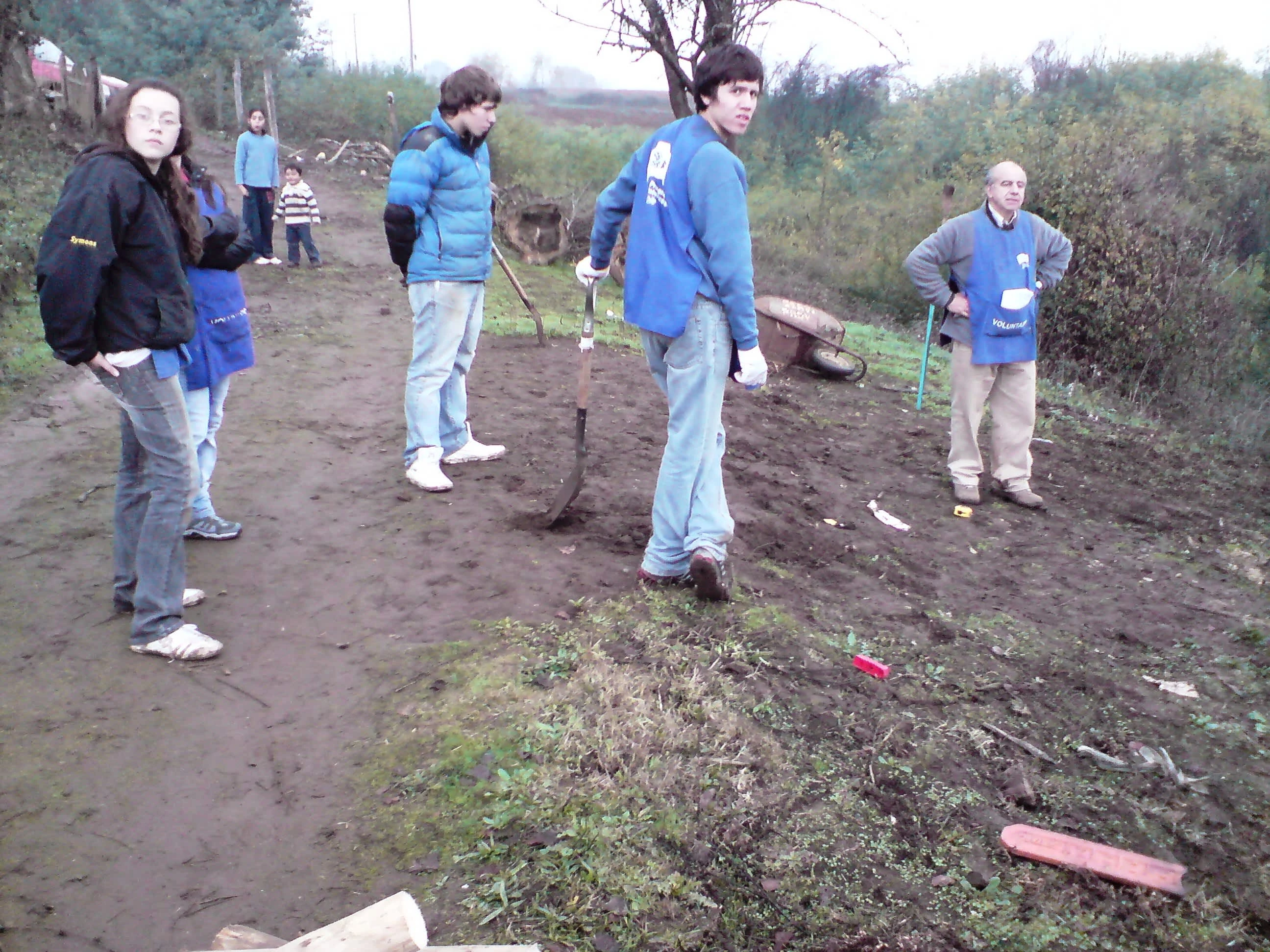
Volunteer team with AFS organizer Roberto Casarejos (right) reviewing the worksite at Los Lomas in the Chilean foothills of the Andes, May 2010. Photo by Ben Angel
Details: Site selection (15-30 minutes)
A mediagua, although prefabricated and assembled with the greatest of care, will still be subject to drafts during cold winter winds. For this reason, its placement is important. Since wind data from nearby weather stations are not generally made available to volunteers for determining the direction of the prevailing wind, the team leader should ask the mediagua owners which direction this is, based on their local experience. This is done during an introductory meeting (the new owner often joins in as a volunteer builder).
Also during the initial meeting, the team leader should advise the new mediagua owner to select a site that avoids obvious hazards and areas that can interfere with permanent reconstruction. The gradient across the mediagua footprint should be such that the base of the highest pile is set in no more than 30 cm in elevation above the base of the lowest pile.
Remember that the owner is a victim of a natural disaster, and most likely will have to house family in whatever is built for some time. As such, if the owner insists on a particular site after the team makes the case for a different location, give in to the owner's wishes (presuming, of course, that all obvious hazards can be dealt with before construction starts).
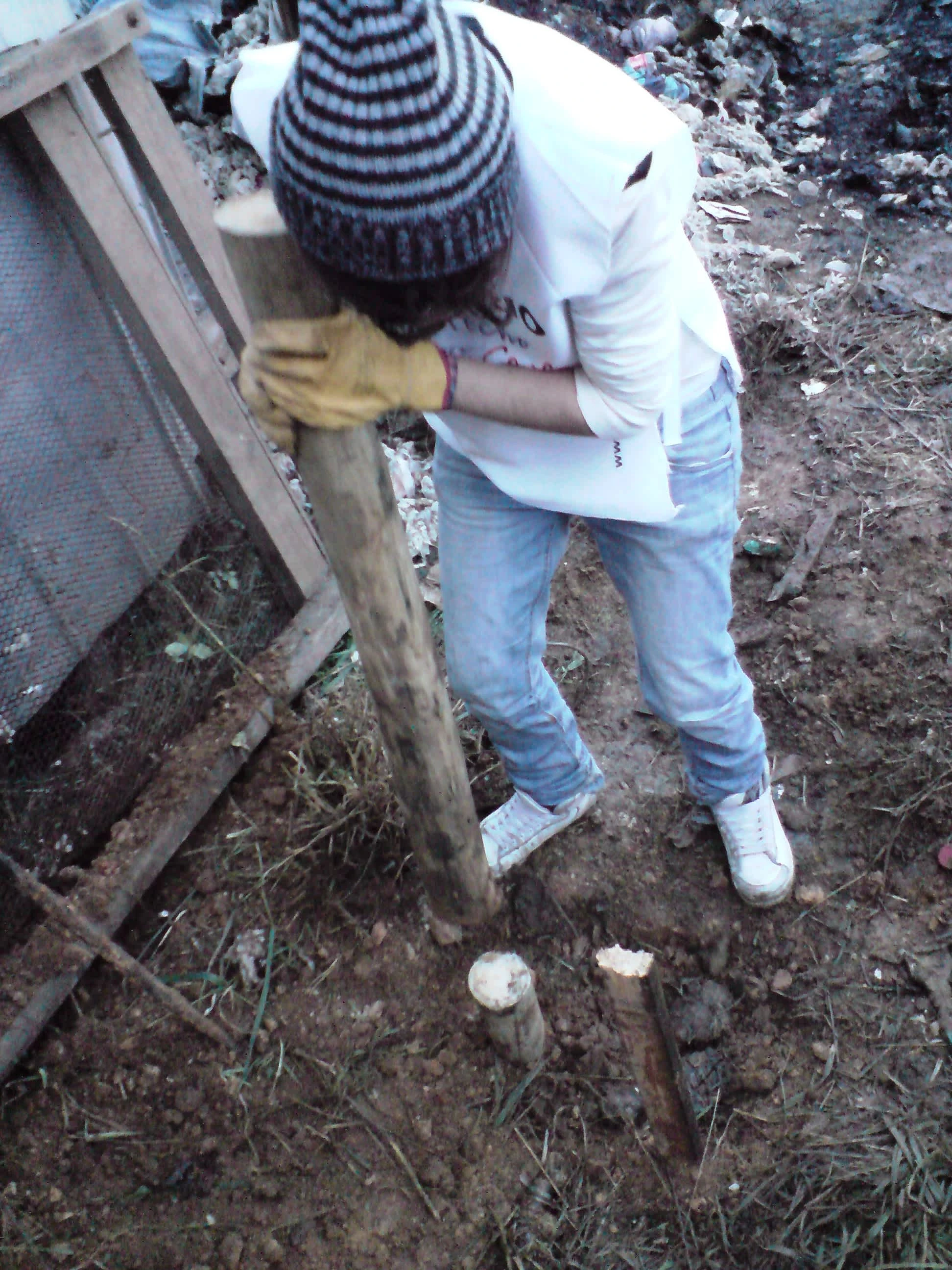
"Pollo," a volunteer builder, setting a pile on higher ground to the same height as the master pile. Mediagua construction at Lota on the Chilean coast, June 2010. Photo by Ben Angel.
Details: Setting the master pile (1 hour)
The master pile (“pilote maestro”) should be set to the lowest corner within the building’s footprint. The reason for this (contrary to what the plans currently say) is that there should be a minimum of two-thirds of all piles, especially the tallest-standing pile, in the soil (50 cm depth, give or take 10 cm). Setting the first pile so that it is in the lowest location allows the others to be either deeper or with less height above the terrain, ensuring the foundation has greater stability (remember that there should be no more than 30 cm elevation between the highest and lowest pile locations).
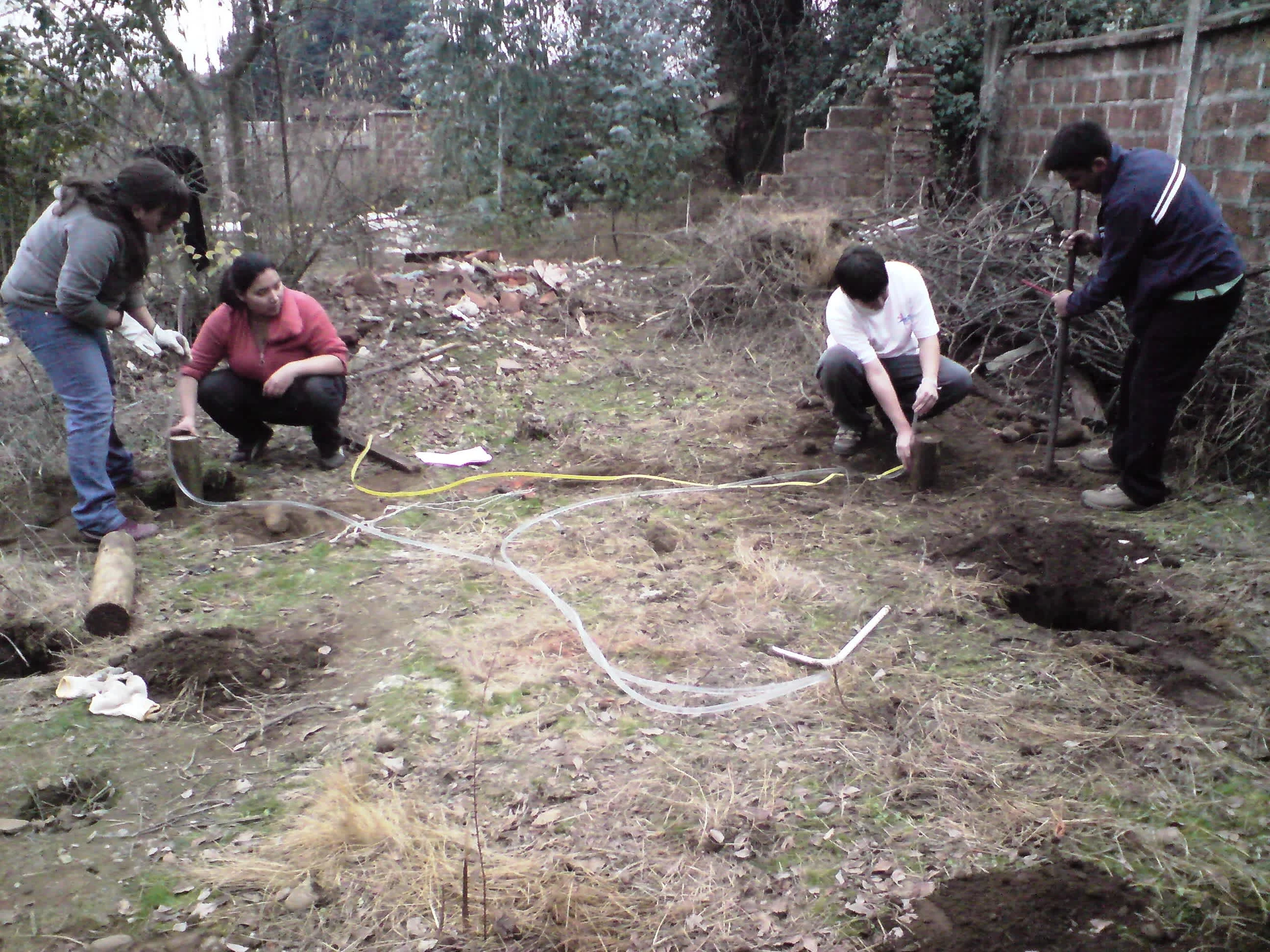
Volunteer team at Linares chicking pile levels using a plastic tube filled with water. If the levels are flush with the top of all piles on both sides, then the floor they support will be even. Photo by Ben Angel, May 2010.
Details: Locating the other piles (3 hours)
The next step in setting the pile foundation is to place the second pile. Most often, this is the corner pile adjacent to the master pile across the width of the footprint (located 300 cm away). This pile needs to be excavated, placed accurately, and backfilled without moving the pile more than a few centimeters from its intended placement.
Accurate placement will be the biggest challenge in setting up the pile foundation. The top of the pile not only has to be accurately placed within a few centimeters of its intended location along the length and width but also the height (a measure that needs absolute precision).
There are two ways to set the height of the second pile. The first way is to measure the height of the master pile above the surface and then dig to a depth such that the top of the second pile is at the same elevation as the top of the master pile; this is checked with a clear plastic hose, partially filling it with water and then holding it so that the water level at one of the ends is set at the height of the master pile (the other end, presuming there are no bubbles in the tube, will be at the same elevation). The second way involves a chain saw – setting in the pile to a depth of roughly 50 cm depth, and then marking where the elevation of the master pile comes to on the second pile (again using the hose) and cutting to height.
Once the first two piles are placed, then the width and depth locations of the other holes can be found mathematically (using the Pythagorean relationship for right triangles). The following “hypotenuses” are presented as a shortcut:
Master pile to the third corner (610 cm length, 300 cm width): 680 cm.
Master pile to the far halfway pile (305 cm length, 300 cm width): 428 cm.
Master pile to the center pile (305 cm length, 150 cm width): 340 cm.
Master pile to the far quarter pile (152 cm length, 300 cm width): 336 cm.
For a 15-pile foundation:
Master pile to the center quarter pile (152 cm length, 150 cm width): 214 cm.
For a 17-pile foundation:
Master pile to the near center quarter pile (122 cm length, 150 cm width): 193 cm.
Master pile to the far center quarter pile (182 cm length, 150 cm width): 236 cm.
Other relationships can be determined through the use of triangles similar to these basic triangles, as observed in the plans.
The method most easily used to find these locations is to use two tape measures simultaneously from set piles; the other pile locations are found by making the tape measures cross at the appointed length and hypotenuse distances.
Other methods for finding pile locations have been tried, including use of chalk line and tracing the floor beams. Typically, these are not as accurate or fast as using two tape measures. The use of a string with knots at the appropriate distances in a right triangle has been tried for a 15-pile foundation, but this too is not as efficient or flexible as using two tape measures.
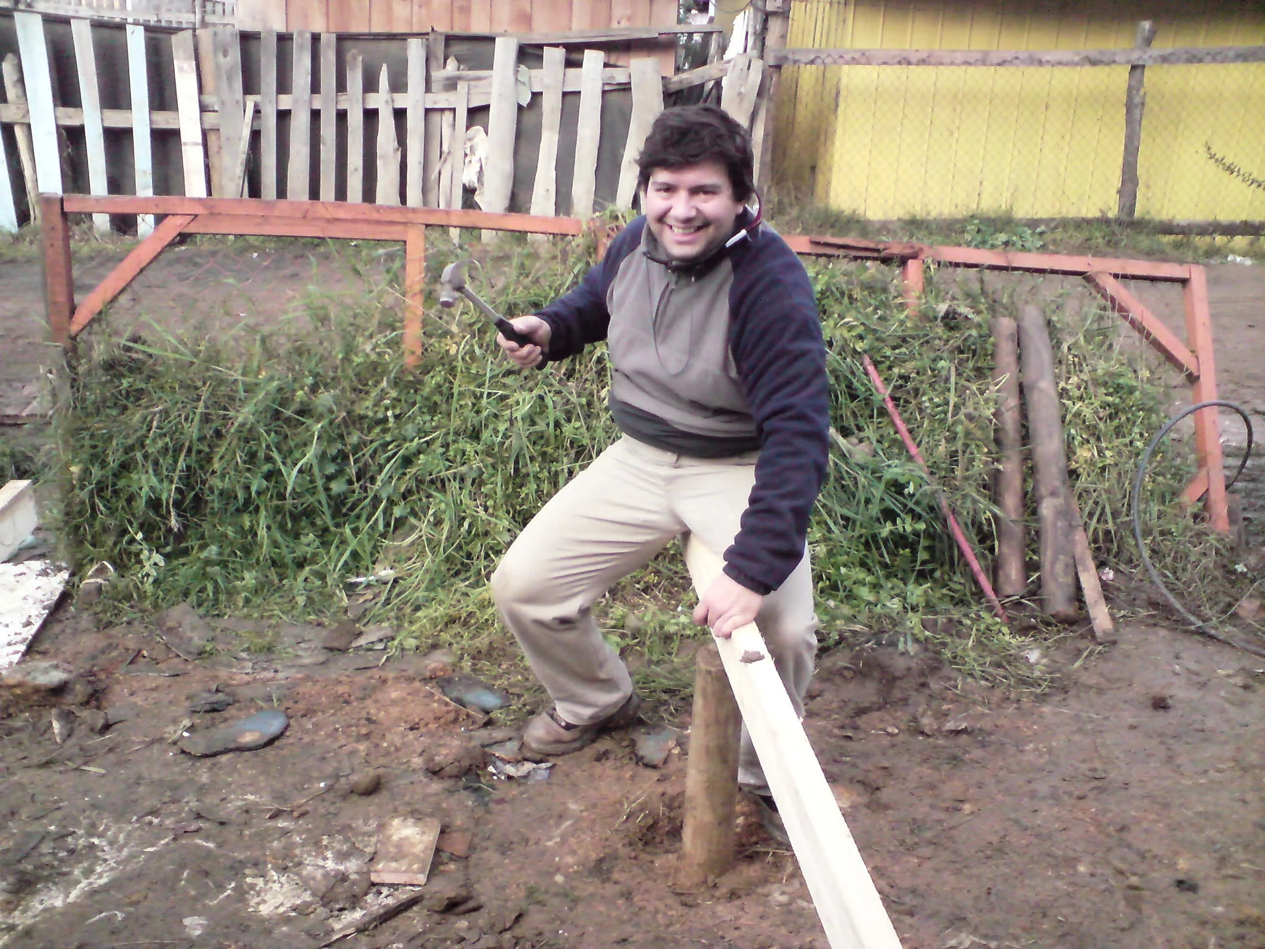
Manuel nailing in a floor beam for a 15-pile foundation at Lota, June 2010. Photo by Ben Angel, June 2010.
Details: Finishing the pile foundation (1-2 hours)
Typically, holes are dug out and piles are backfilled into position one or two at a time so that almost at the same time that they are located, piles are emplaced. But as they are placed, the piles should be checked to ensure that their tops are at the correct elevation and the correct location laterally.
The process for placing the pile is to dig to the appropriate depth (whether using the dig-to-depth or cut-at-height method), place a layer of rocks in the center of the hole, and smash these rocks into the dirt so that there is a “floor” beneath the pile. (The plans say that this layer of rocks should extend under the entire hole, as it will somehow serve as a spread footing for the pile. Although the designer meant well, a gravel spread footing simply would not serve any purpose as it is not rigid. However, a layer of rocks under the pile would serve to temporarily slow the settlement of the soil below it.)
After the pile is in place, it should be measured horizontally to ensure it’s at the right location, and its elevation should be checked against the master pile. Once the pile is in the right place, backfilling can begin.
Pile backfilling is an area that is frequently neglected. Proper backfilling is done in stages – placing in 15 cm of fill, and then compacting, then another 15 cm, then compacting. Typically, a spare pile is used to compact the fill in the annular, though a pry bar can be used if the space between the pile and the edge of the hole is not wide enough for a second pile to fit while compacting.
The three reasons by which teams have most frequently failed in getting the foundation right have been:
Failing to measure from the external side of the outer piles to the center of the inside piles (the floor panels should land on the outside of the external piles, and share the middle row of piles; in a 17-pile foundation, the pile also needs to be placed so that the beams at 122 cm and 182 cm land at the center of the pile).
Failing to keep the pile in its location while backfilling and compacting.
Failing to check the elevation of the top of the piles after setting and before placing the floor.
If a 15-pile foundation is designated for the mediagua, a set of six 2×4 beams will likely be provided. The plans call for cutting the beams so that they diagonally fit one on the other on the center piles, but this has been called unnecessary by some organizers. The idea of the diagonal cut is to attempt to keep the beam as close to one piece as possible. If the soil seems unlikely to settle, this can be safely dispensed with (the diagonal cut has to be exact, and can be time-consuming if power tools are not available). Again, the external beams should be on the outside of the piles, while the internal beam should be in the center of the middle row of piles. Also, the beams should be nailed to the pile through the beam’s sides (diagonally) rather than from the top, to avoid nail-on-nail issues when nailing the floor to the beam.
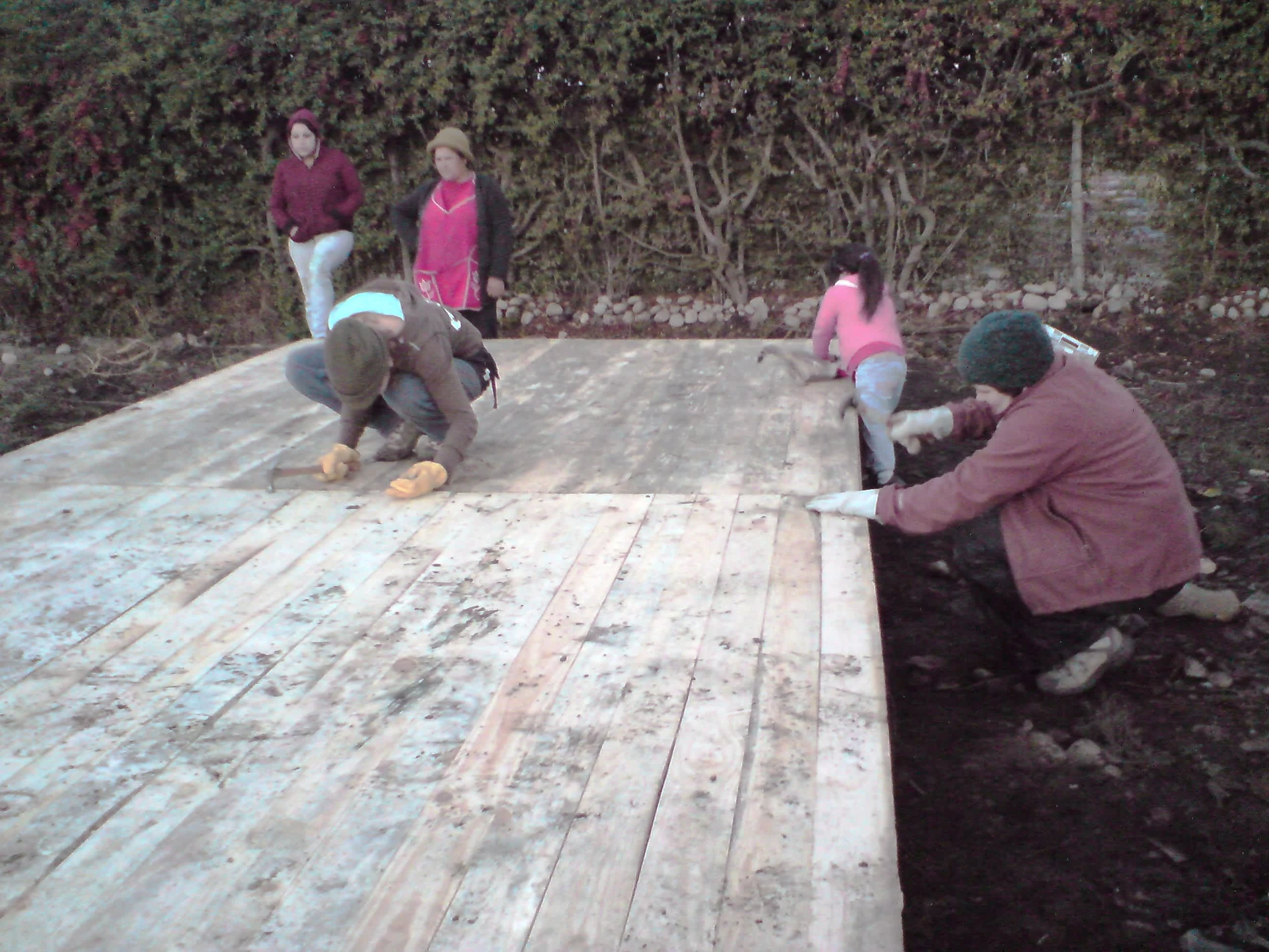
Setting the floor for a mediagua at Romeral, Chile, May 2010. Photo by Ben Angel.
Details: Floor placement (30 minutes)
If everything has been done correctly to this point, the floor (“piso”) should fit exactly over the pile foundation (whether with pile beams or not). It’s not uncommon to find something has been done incorrectly, particularly if the last piles are placed in as daylight starts to fade beyond the end of the civil twilight. Needless to say, if the floor doesn’t fit exactly, corrections need to be made.
Once the floor fits perfectly, the next step is to nail it with the 6-inch floor nails (“clavos grandes”) to the pile foundation. All pile locations should have a floor nail (whether there is a foundation beam or not). The floor is also made more stationary if nails are hammered in at diagonals along the center so that the two floor pieces are connected. Ideally, the floor pieces should come together without any gaps. (Often, this is where the team will find the first clue that the panels are not well put together by the factory that donated them. The advice for this situation applies to installing all the panels – work with what you have.)
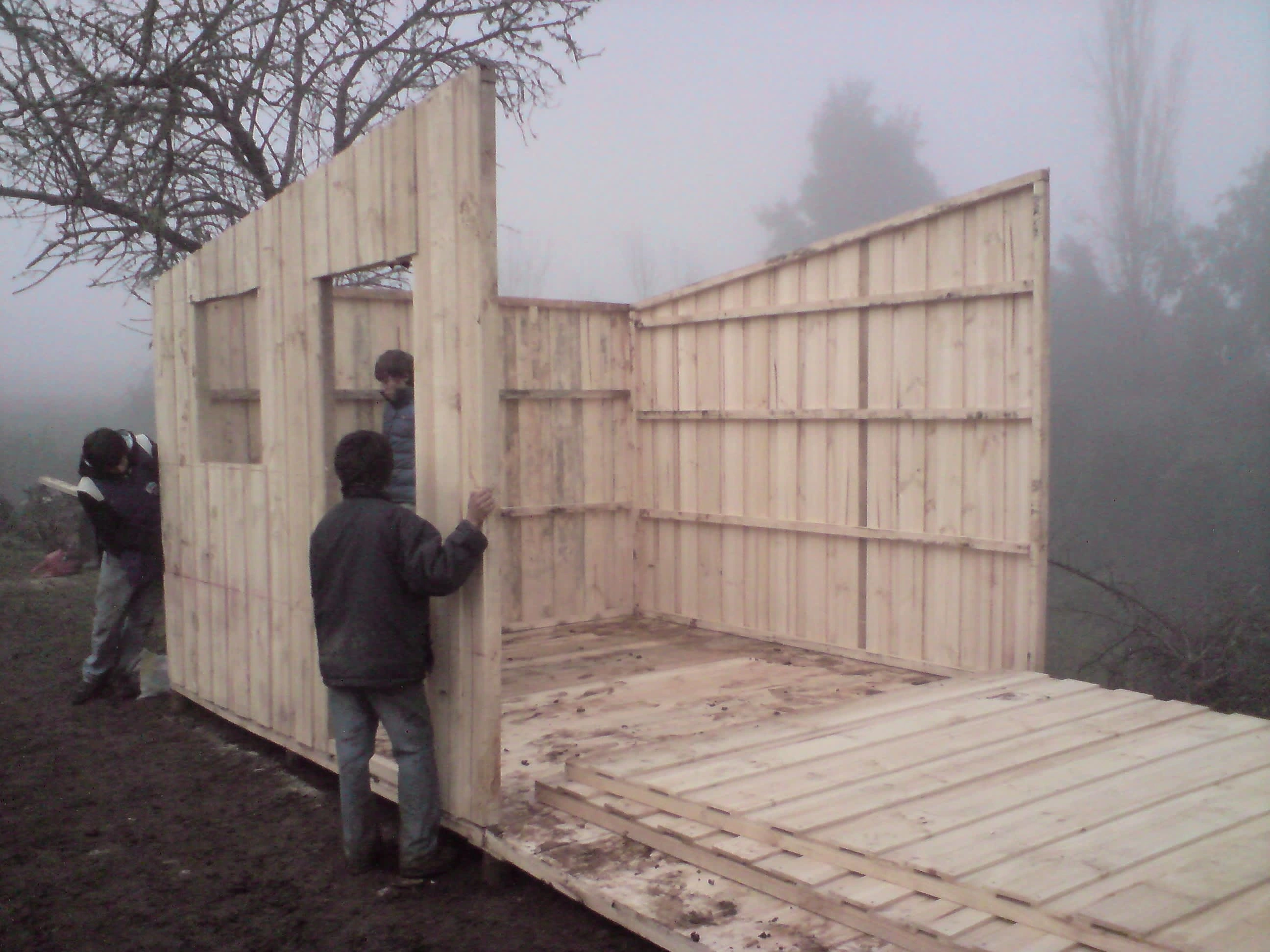
Wall-raising at foggy Los Lomas in May 2010. Photo by Ben Angel.
Details: Raising the Walls (1-2 hours)
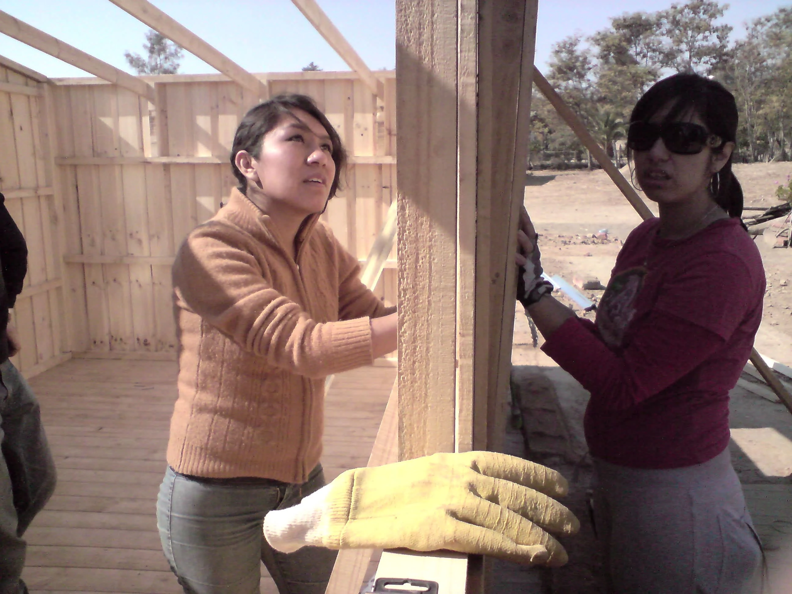
This stage varies greatly in duration, depending on the quality of the construction of the side panels. The most efficient method for placing the walls is to stage them in the center of the floor, with one set of side-back-front panels on top of the other (front panel below the back, which is below the side).
The first two pieces to be raised are the side and back panels. These should be nailed together while being kept loose on the floor; the two panels must be able to move about on the floor if needed, either horizontally or vertically, until all the sides are put together. Volunteers should ensure that the side panels are set so that the third with separations into four spaces is on top.
Nailing should be done so that the nails go diagonally into the two 2×2 beams that connect (the external planking should be ignored when putting the two pieces together). A trick to getting the two pieces together tightly is to have two people hammering simultaneously – one hitting the nail, and the other hitting the wood from the other side so that the two pieces come together without gaps. If there are any differences in height between the side and the back (or the side and the front), the top beams should be closer to meeting each other than the bottom beams.
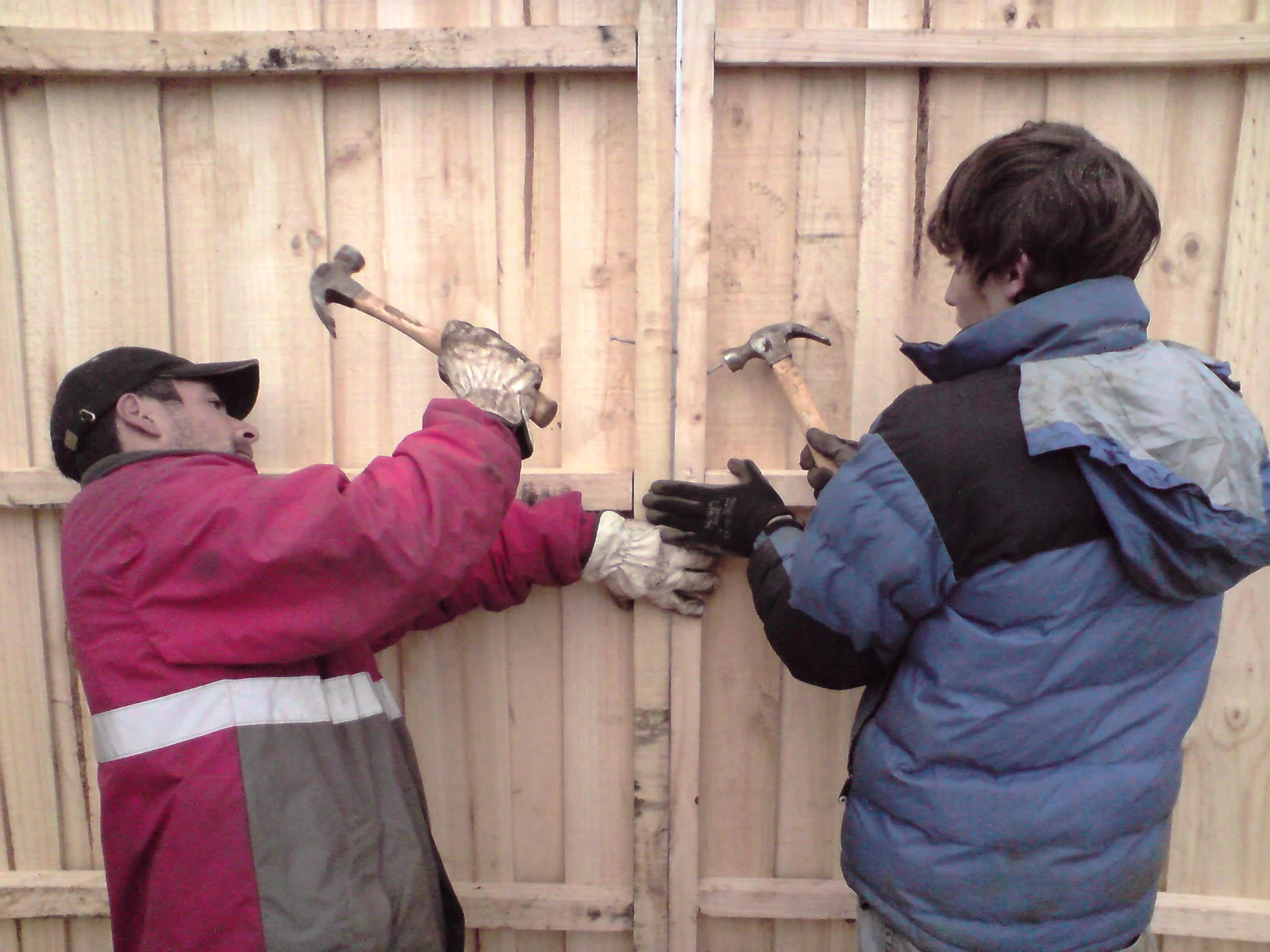
Alejandro and Ubaldo fixing a gap in the wall between two sides of a mediagua using a diagonal nailing technique. Los Lomas in May 2010. Photo by Ben Angel
The front should likewise be nailed to the side panel while being kept loose on the floor. The same nailing techniques apply. Once the first “U” is in place, the panels should be moved so that the 2×2 beams are on the very edge of the floor. Then work can begin on the second “U”.
Once both U-pieces are in place, the centers are nailed together. This is not always an easy task, as it is common for the front and back panels to come from the factory with one side or the other much smaller than what the plans call for. This creates a situation where either the inside of the front or back, where the pieces are nailed together, is off the floor by several centimeters, or where the ends of the front or back, where they connect to the side, are off the floor. Often, the wall looks like a lost cause, but the problem is still correctable, even without having to take apart the errant sides (as some teams have tried).
This is where not having nailed the sides to the floor pays off. If the center is off the floor, nail starting from one of the sides going inward for short distances at a time. Nails may need to be hammered several times to push the lower beam to the floor (ensuring that it always is flush with the outside of the floor). If the sides are off the floor, then nailing starts from the center and progresses outward, with both sides being held up at first with pry bars to evenly distribute the stretching of the structural pieces at their ends.
There should be no gaps between the floor and the sides before work progresses to the next stage – the start of the roof and the terminal items (doors and windows).
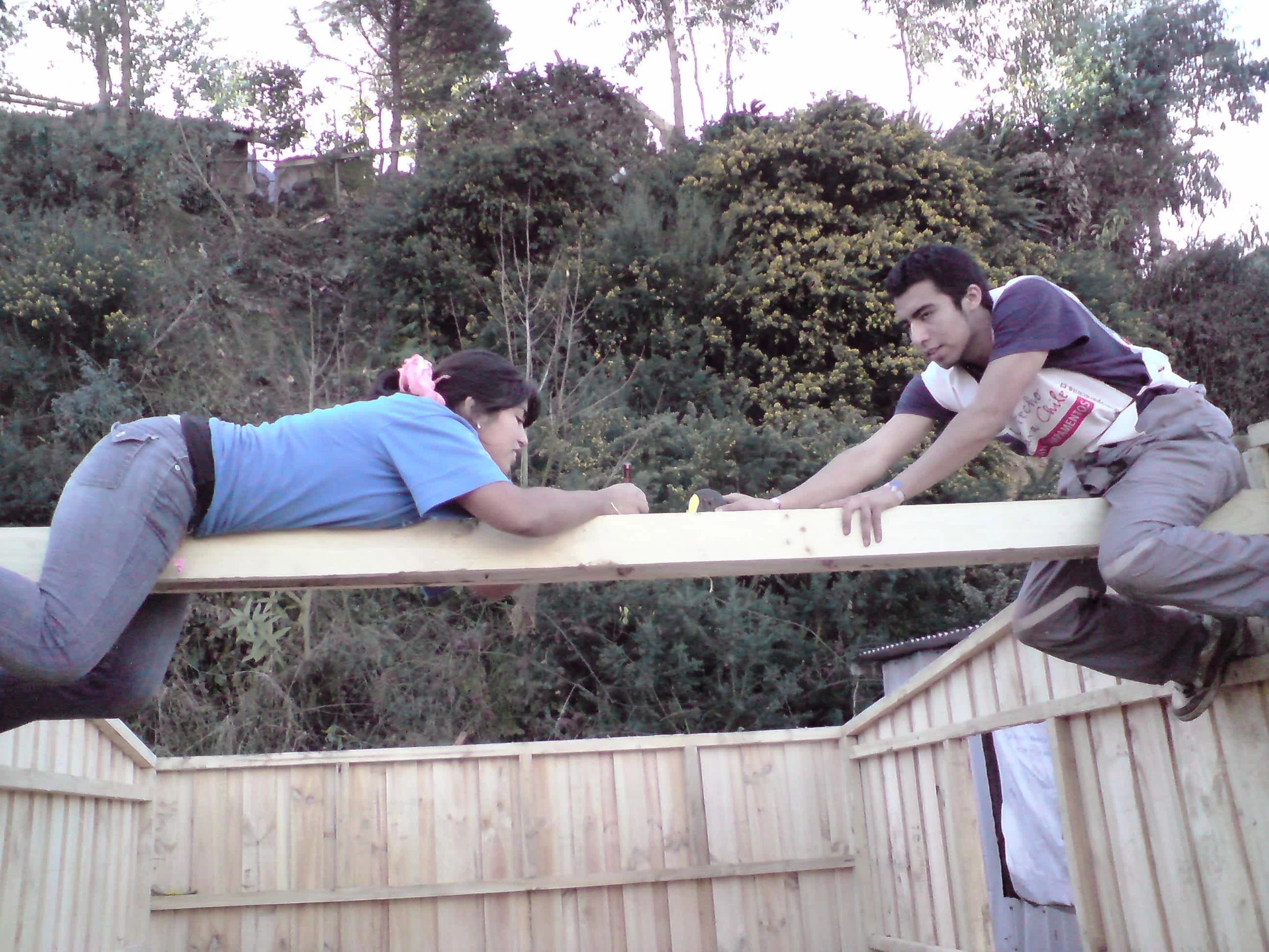
Setting the main beam at Lota, June 2010. Photo by Ben Angel
Details: Installing the main beam (30 minutes)
The main beam (“vigas maestro”) holds up the entire roof. It consists of two 3-meter-long 1×4 beams running parallel to each other from either side of the centers, with three spacers (“tacos”) located where the secondary beams connect. It is installed 11 cm down (the width of a 1×4) from the structural 2×2 beams at the edges of the front and back using the smaller nails (“clavos chicos”).
The first step to installing the main beam should have already taken place by this time – cutting the rafters (the 6-8 pieces of 2×2 lumber) to 2.9 meters length. The reason this must take place before work begins on the main beam is that the pieces that have been cut off (called “chongos”) are to be put together to create the three spacers. These should be 20-22 cm in length, and consist of two “chongos” nailed together.
The plans read to have the spacers placed at 74 cm from the ends of the main beam, and 69 cm from each other in the center. This is to match the position of the beams on the side panels. However, the side panels are rarely constructed correctly, and attention has to be paid to ensure that the spacers are placed in such a way that the secondary beams are square to both the side panel and the main beam (the reason for this being the slight possibility of the secondary beams twisting under load). An additional spacer piece for the main beam may need to be cut if the side panels are very badly constructed.
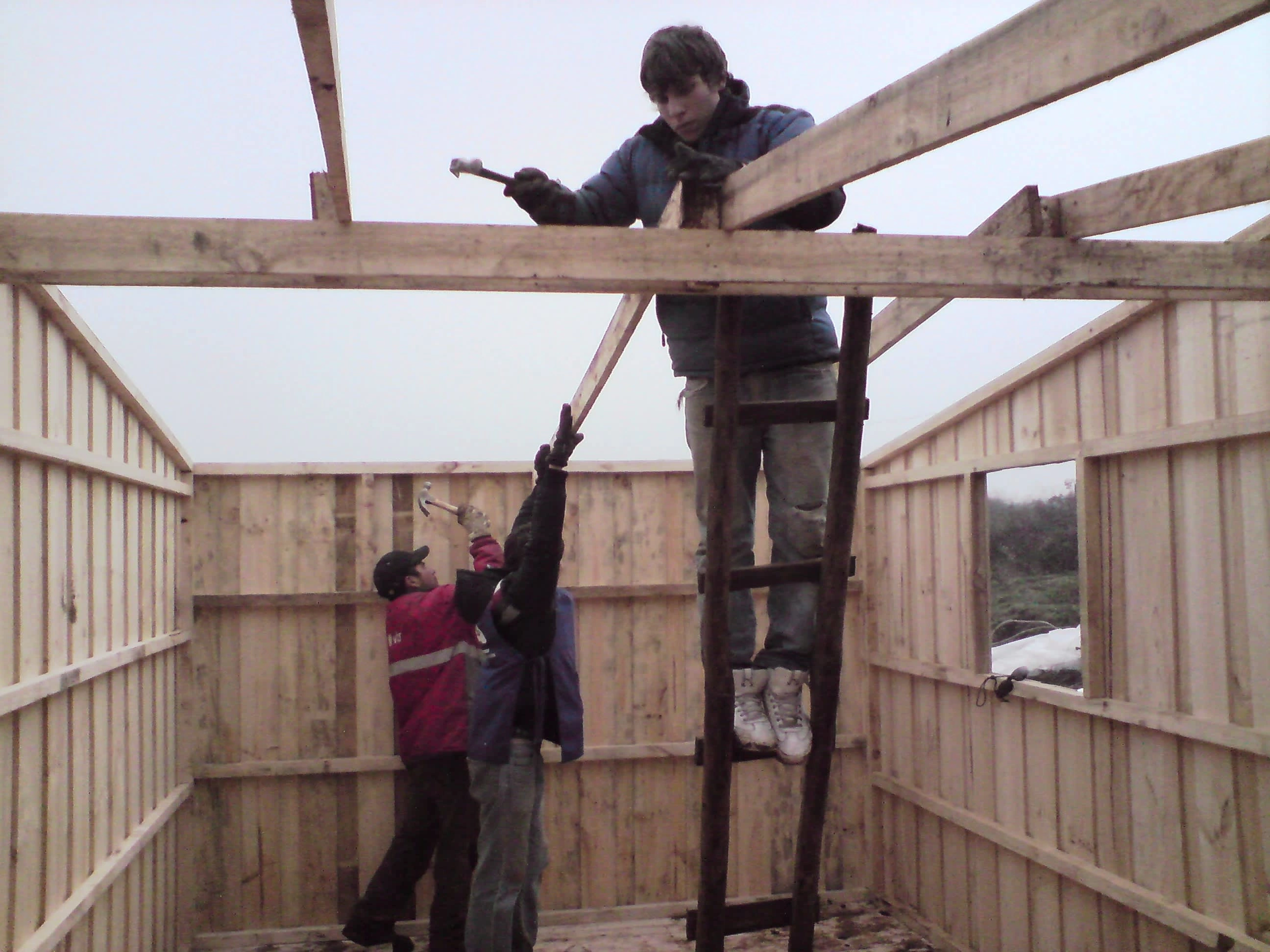
Setting secondary beams off of the main beam at Las Lomas. Photo by Ben Angel.
Details: Installing the secondary beams (30 minutes)
Often, the secondary beams (“vigas secundaria”) are simply 1×4 beams cut to 3.13 meters and hammered in place between the side panel and the spacers, with someone taking an axe to the resulting points sticking up from the secondary beams later. Much more aesthetic is the idea of fitting the secondary beams in place, then tracing the outline of the spacer onto the beam before having it cut (preferably with a power tool). Naturally, the secondary beam placement would have to be kept in order, since outlines may differ from spacer to spacer. The secondary beams, when installed, should be positioned so that they easily hold up the rafters, which are placed onto the roof structure next.
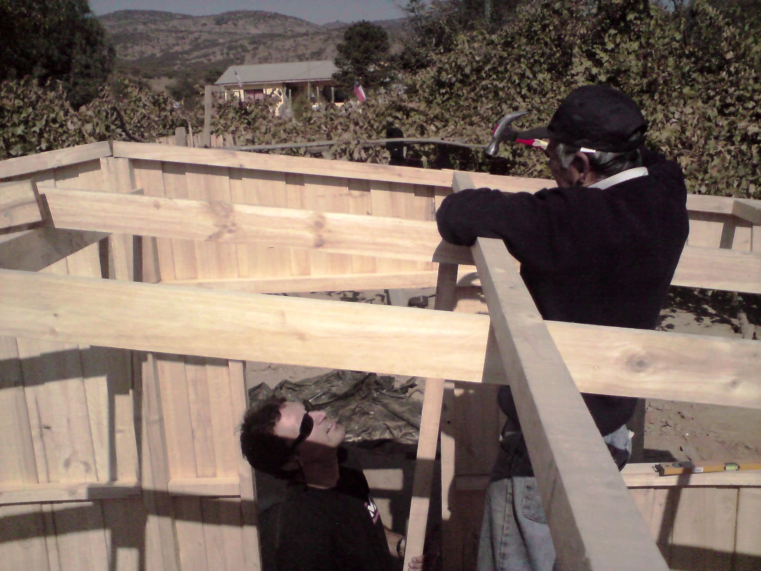
Don Antonio and Marc installing rafters off the secondary beams at Los Coipos, April 2010. Photo by Ben Angel.
Details: Installing the rafters (30 minutes)
The rafters (“costaneras”) are the last wooden element of the roof left to be installed. These 2.9-meter-long 2×2 pieces were cut in the making of the main beam. They are nailed in both to the sides and onto the secondary beams at intervals from the top structural beam on the front and back, based on the number of rafters to be installed:
Six-rafter configuration: 10 cm, 105 cm, 90 cm.
Eight-rafter configuration: 10 cm, 73 cm, 72 cm, 72 cm.
Once the rafters are installed, those volunteers working on the roof will begin laying in tar paper (“fieltro”) and the aluminum zinc roof (“zinc”). However, while the roofing crew has been working, a team should also be working on the terminal elements, or rather, the windows and the door.
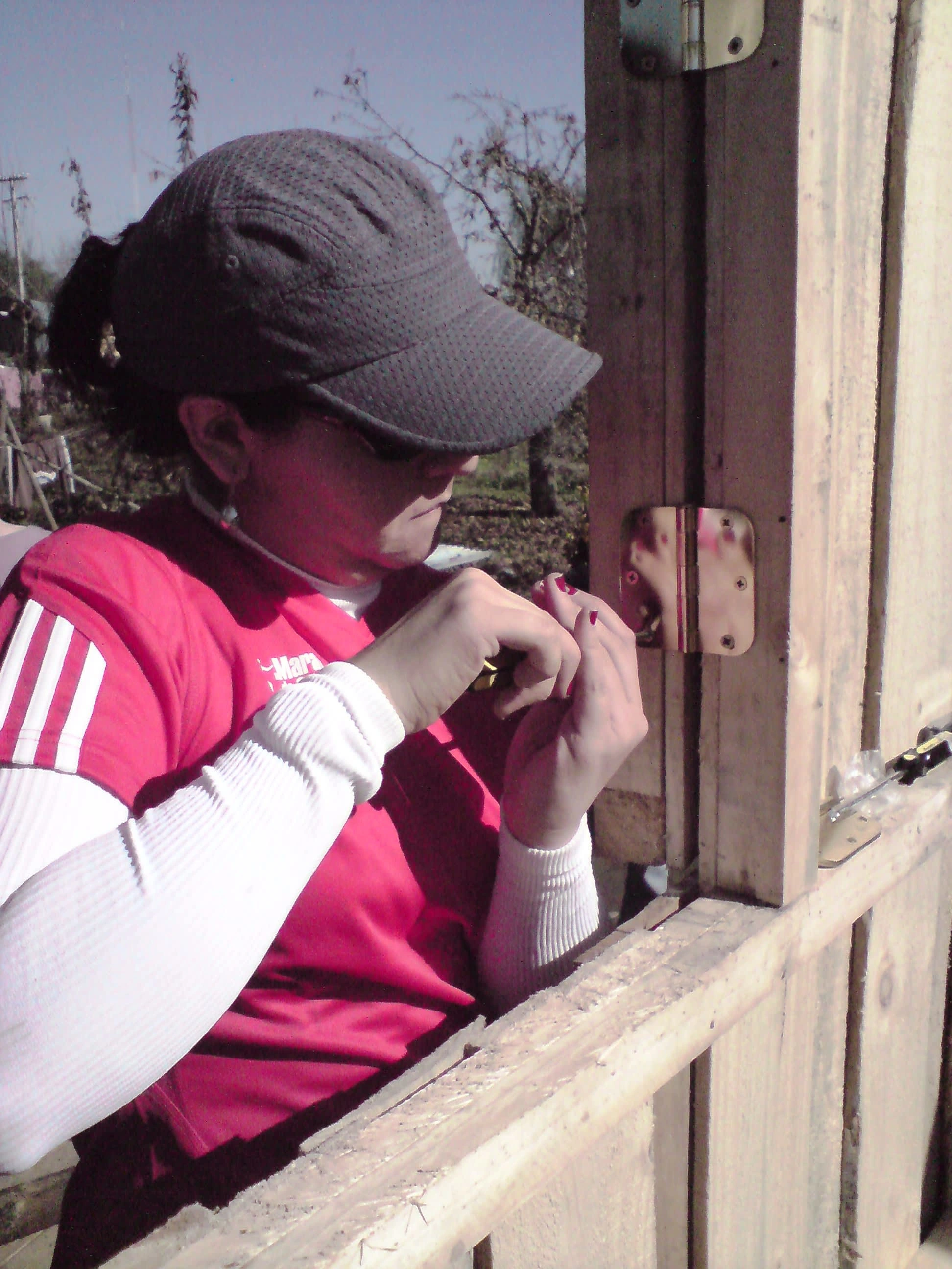
Ivana and Danila fitting in a door at Los Coipos, April 2010. Photo by Ben Angel.
Details: Terminal elements (2 hours)
The first step in the installation of the door (“puerta”) and windows (“ventanas”), or terminal elements (“terminales”), can take place shortly after the sides are nailed to the floor. The lower 2×2 beam that holds the two sides of the door in place is cut and removed. This 2×2 can be used to add reinforcement to the main beam, placing a block below each beam along the front and back connection (this additional support is not in the plans, but seemed a good idea to add support to an element that holds up the entire roof).
After the door jamb is cut out, the next step is to check to see if the window shutters fit into their windows. If the window shutters and front panels are constructed correctly, this becomes a routine check. As has been mentioned in this set of instructions, the wooden panel pieces are frequently not constructed correctly, and so those who are installing the windows may need either to take apart and reconstruct the window shutter or the frame to ensure that the shutter fits.
The next concern is the direction in which the doors and windows open, in particular, the door. Traditionally, doors in Latin America opened inward, apparently to allow the wood to stay dry (and avoid warping or otherwise deforming) if left open in the rain. However, doors outside of Latin America (in particular in the United States, where the National Fire Safety Association construction code is in use), open outward so that in case of fire, it is easier for people inside to push outward against the door and escape. The best that a volunteer can do is give strong advice to have the door open outward, for the safety of those who will be living in the mediagua. (Windows, on the other hand, are not as critical to fire safety, and can open either way – how they open should depend on how the new owner of the mediagua wants these to open.)
Windows being set in at Romeral, May 2010. Photo by Ben Angel.
After the directions in which the door and windows open are established, work begins on installing the hinges (“bisagras”). These should be installed first onto the door or window shutter. The plans dictate that the shutters should be 10 cm from the top and bottom of the window, and on the door, these should be 15 cm from the top and bottom of the door. The door should have more than two hinges (with the center hinges spaced evenly between the top and bottom hinges). Construction organizers should be required to not skimp on door hinges, but it is not unusual to find that only six hinges (two for each terminal element) are provided for construction. The reason that the door must have more than two hinges is that it is very heavy (much heavier than the windows), and the door is very likely to fall off in a short period (sometimes even during construction) if only two hinges are used.
(An effective solution that constructors can apply if the door is given only two hinges is to nail into place one of the shutters, and install the shutter hinges onto the door – the door will be used much more frequently than the windows. After that, advise the new owner to get hinges for the second window.)
Often, the terminal elements are set with very little space between the frame and the door or window shutter. For this reason, teams are advised that when the space between the frame and terminal element is tight, chisel out where the hinges connect to the door or window, and the frame. This should allow the terminal element to open more freely. However, be aware that some windows and doors are constructed much smaller than the frame in which they are meant to fit. In such instances, chiseling out the hinge is not advised. (On rare occasions, one hinge may connect where the terminal element fits tightly, and the other hinge where it fits loosely – in which case, the tighter hinge should be chiseled out while the loose hinge should not.)
If manually screwing in the hinges (as opposed to using a drill), use a nail to create a pilot hole for the screw – this is done by hammering in a nail 3-4 times, then pulling the nail out. This allows the screw to go in much easier than if just trying to insert the screw into the wood without a pilot hole.
The last elements to install are the bolts. Ideally, there will be three sets of bolts, one for each terminal element, but again, this may not be provided by team organizers. If that is the case, then there is little that the team can do other than advise the new owner to buy them and install them later.
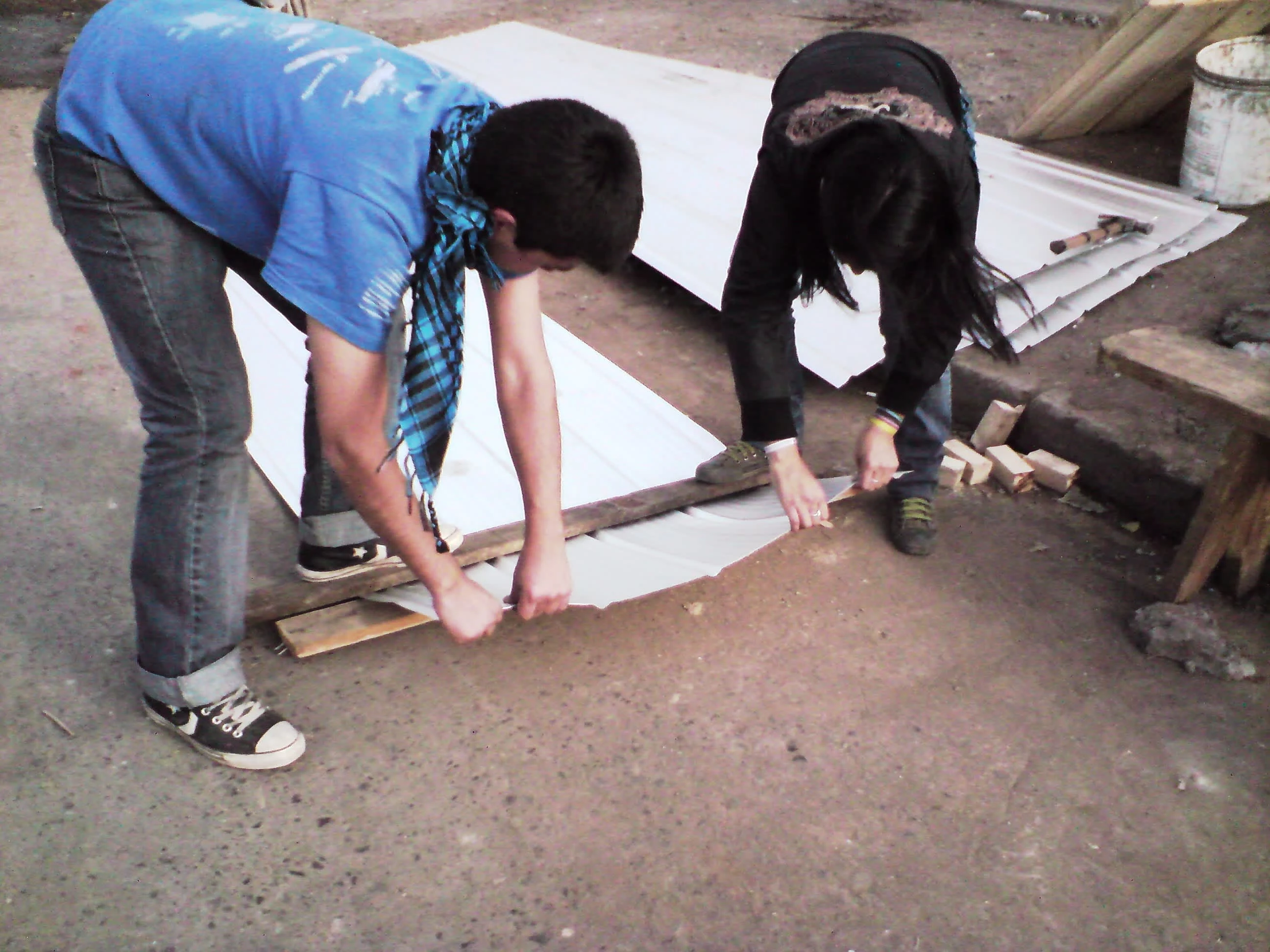
Bending the zinc roofing into a gable using a plank. Mediagua constructed near Estacion Central in Santiago, June 2010. Photo by Ben Angel.
Details: Tar paper and zinc roofing (2-3 hours)
The roofing material consists of two main elements: tar paper (“fieltro”) and aluminum-zinc corrugated metal panels (“zinc”). The tar paper goes below the zinc roof as protection against condensation from internal humidity (the natural result of people inside exhaling). The zinc is sized so that it should provide coverage for the entire mediagua.
Occasionally, flashing (“tapajuntas”) is provided to cover the very top. When it is not, the zinc roofing pieces (3.4 meters in length) are to be bent over the last 40 centimeters of length. This is best done before the rafters are placed so that the 2×2 wood can be used to gauge when it has been bent roughly 15 degrees (the 40 cm segment should extend downward 5 cm, or the width of a 2×2).
Although not specified in the plans, the roofing material should be done in such a way that the zinc is installed almost immediately on the tar paper, particularly if it is raining during installation. This means setting in one strip of tar paper and then placing the zinc over that as soon as the tar paper is secured to the frame.
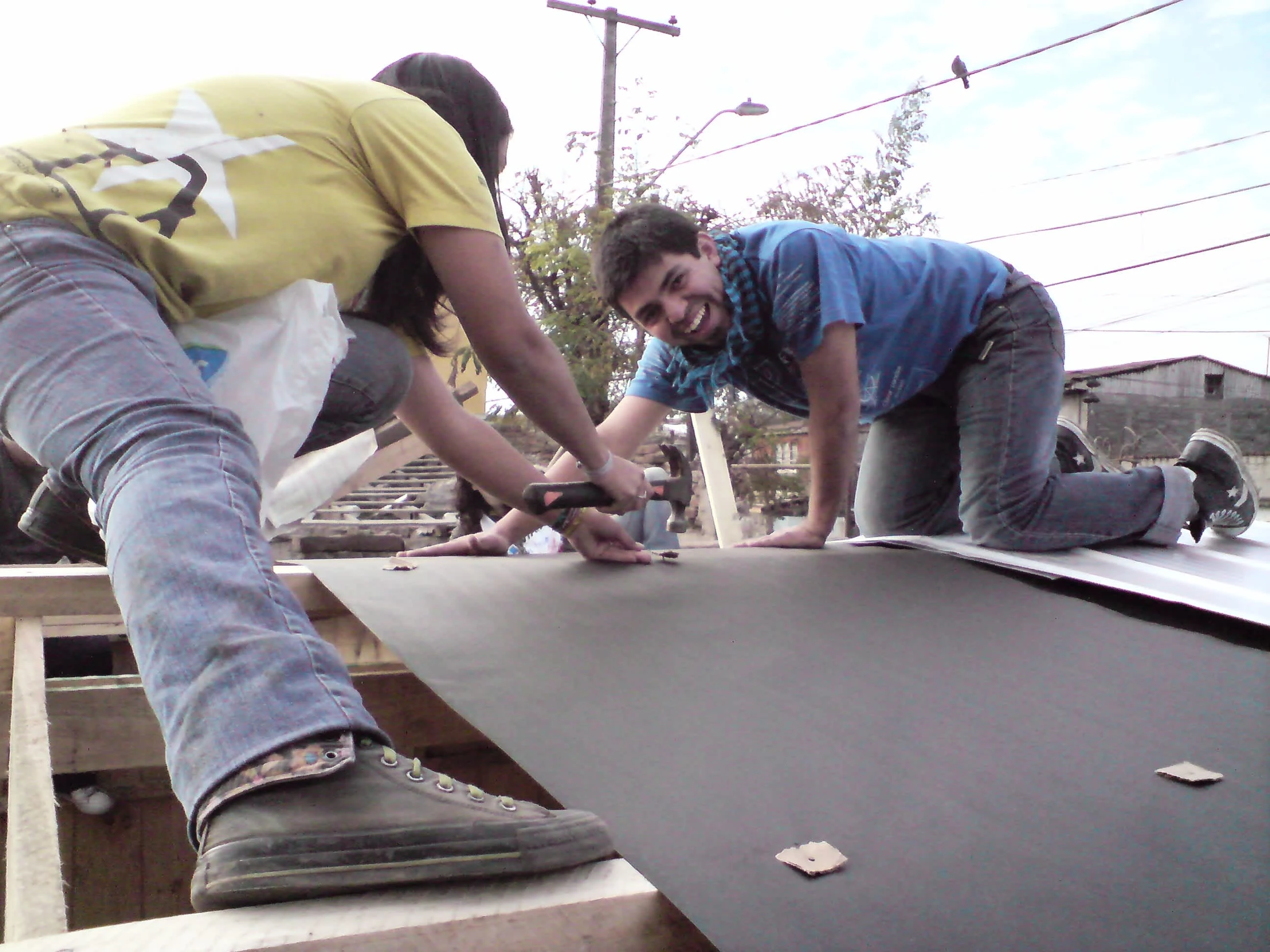
Tacking in tar paper onto the rafters at a mediagua near Estacioni Central in Santiago in June 2010. Photo by Ben Angel
The tar paper is often secured to the frame using small tacks (“tachuelas”) that are provided by organizers. For the tacks to work, they have to also pierce a small piece of cardboard, or else the head of the tack will invariably rip through the tar paper. A way around the tedious and time-consuming task is to use a staple gun to secure the tar paper to the frame – the tar paper generally won’t rip through staples (“grapas”).
In installing the tar paper, it is very important to ensure that it is tight, not only for aesthetics but also because slack bulges in the tar paper will allow moisture from condensation to collect and drop back into the structure. Further, care must be taken in getting the paper onto the roof, as it tears easily. (One of the best methods observed for this has been to roll the tar paper into a scroll, with half going from the center down one side, and the other half going down the other side.)
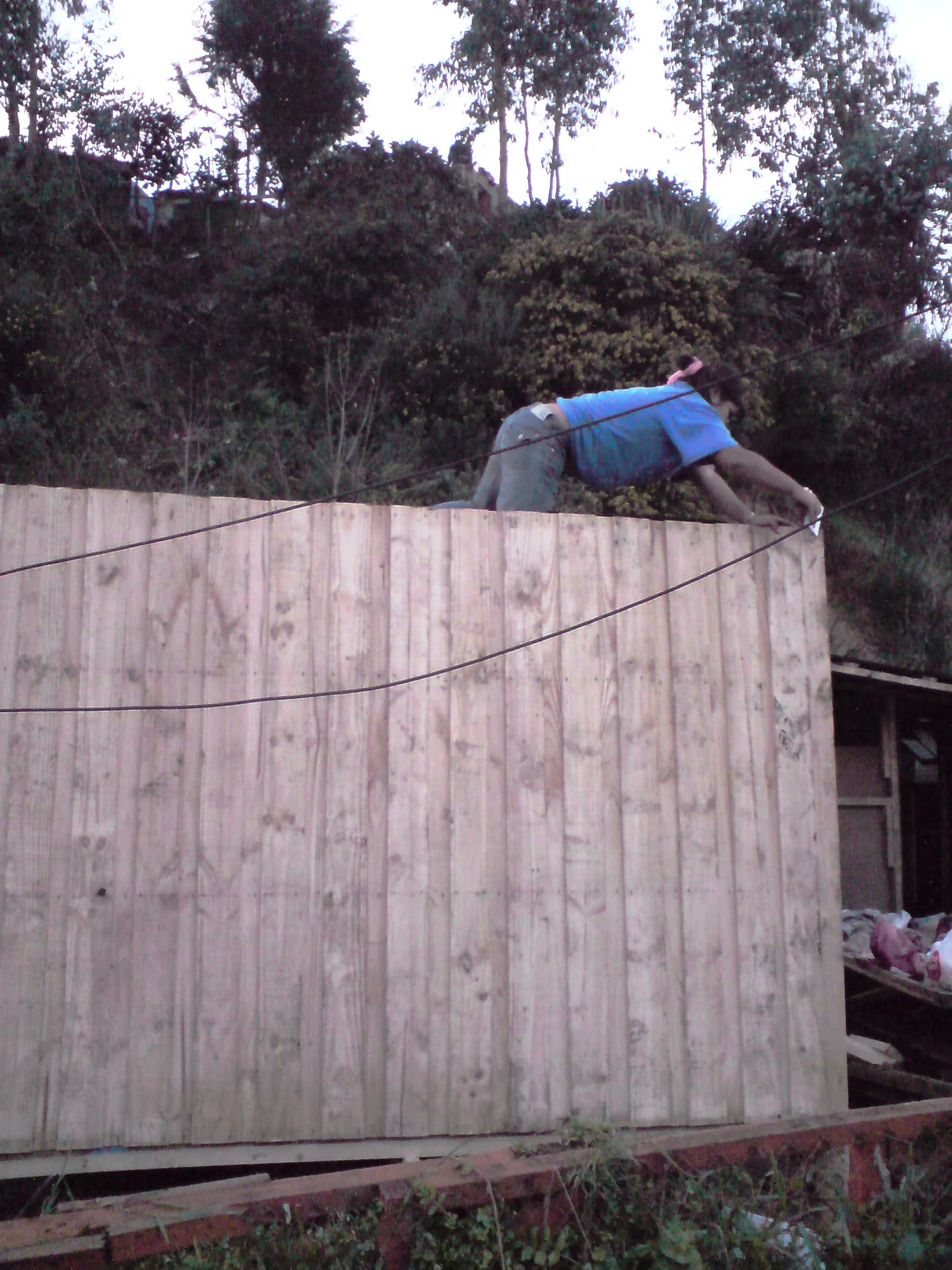
Stapling in tar paper onto the roof of a two-mediagua living place at Lota, June 2010. Photo by Ben Angel.
Once a row of tar paper is set in, the zinc roofing can be nailed to the structure. The first roof piece should be set so that one ridge of corrugation separates the edge of the metal from the beam on which it is to be nailed (and if flashing is not provided, then so that the 40 cm bent segment fits over the far-side of the gable). Only roofing nails (“techados clavas”) should be used to place in the metal pieces (these are square nails that are twisted, and which have a special washer at the head). Nails connecting the outside beams should be inserted at the groove (and nailed in tight). Nails going into interior rafters should only be inserted in at the ridges (avoiding water from the grooves from going in under the washers). Finally, it is necessary to wait to nail the inner side of the roofing until the next layer of tar paper can be inserted (the tar paper must be overlapped, which means that part of it goes under the metal that is being nailed in).
The second row of tar paper is installed much the same as the first, again with part of the paper overlapping under the first row of zinc. The second row of zinc is installed with one ridge overlap, again with the roofing nails going through the top of the ridge. The third and fourth rows follow the same pattern. Finally, the flashing is installed, again with roofing nails going through only ridges in the corrugation.
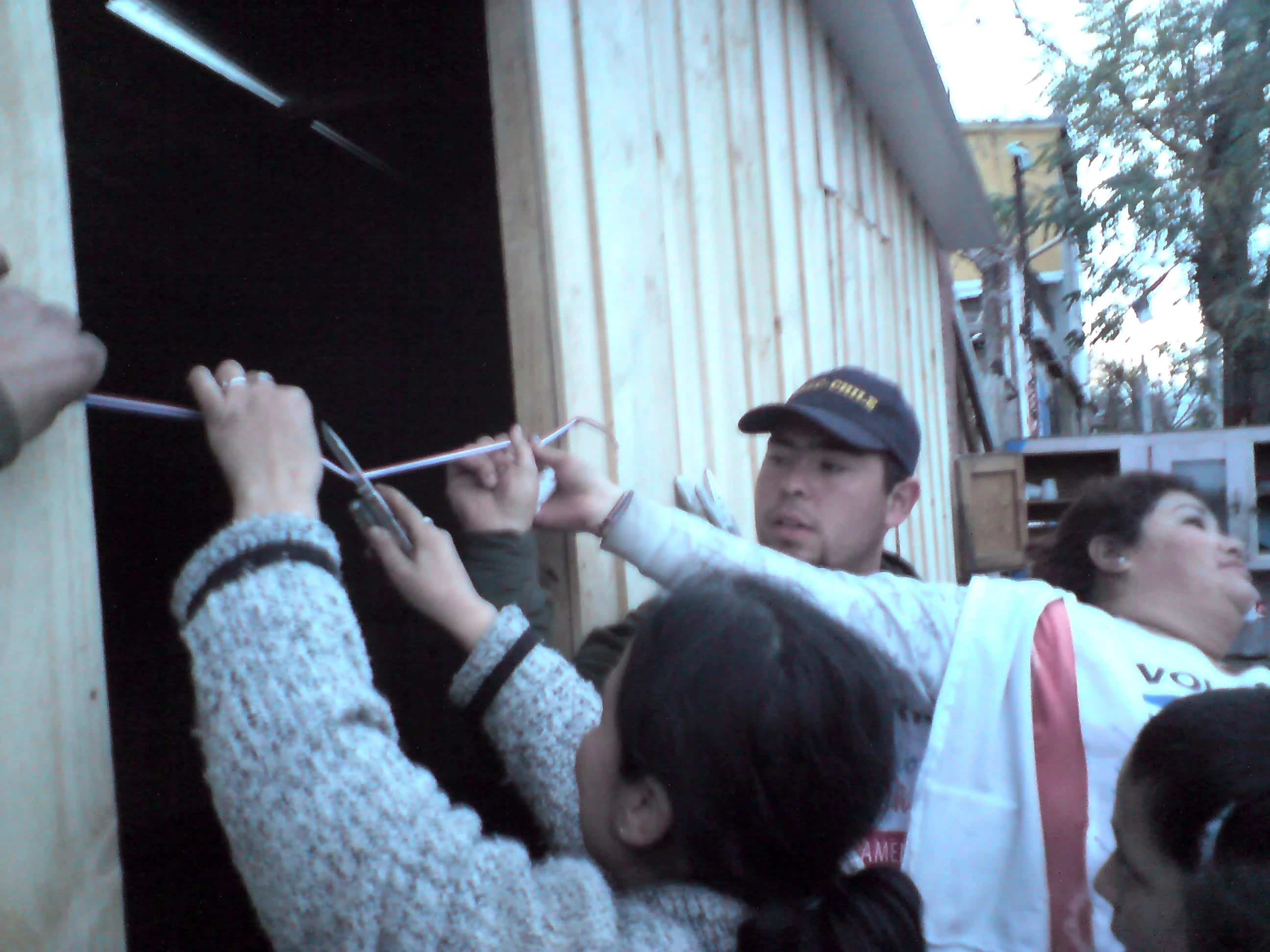
Ribbon cutting on a new mediagua, completed near Estacion Central in Santiago, June 2010. Photo by Ben Angel.
Details: Finishing ceremony
There is no set method for “christening” a completed mediagua. This is pretty much left to the team (some organizers provide ribbons and medallions – the medallion is installed on the door, and the ribbon is used in a cutting ceremony). Ideally, the team will have cleaned up the inside of the structure for turnover, as well as the grounds around the structure, if practicable. Any spare material should be neatly stockpiled if to be left at the site. Of course, tools and personal belongings should be collected before departure.
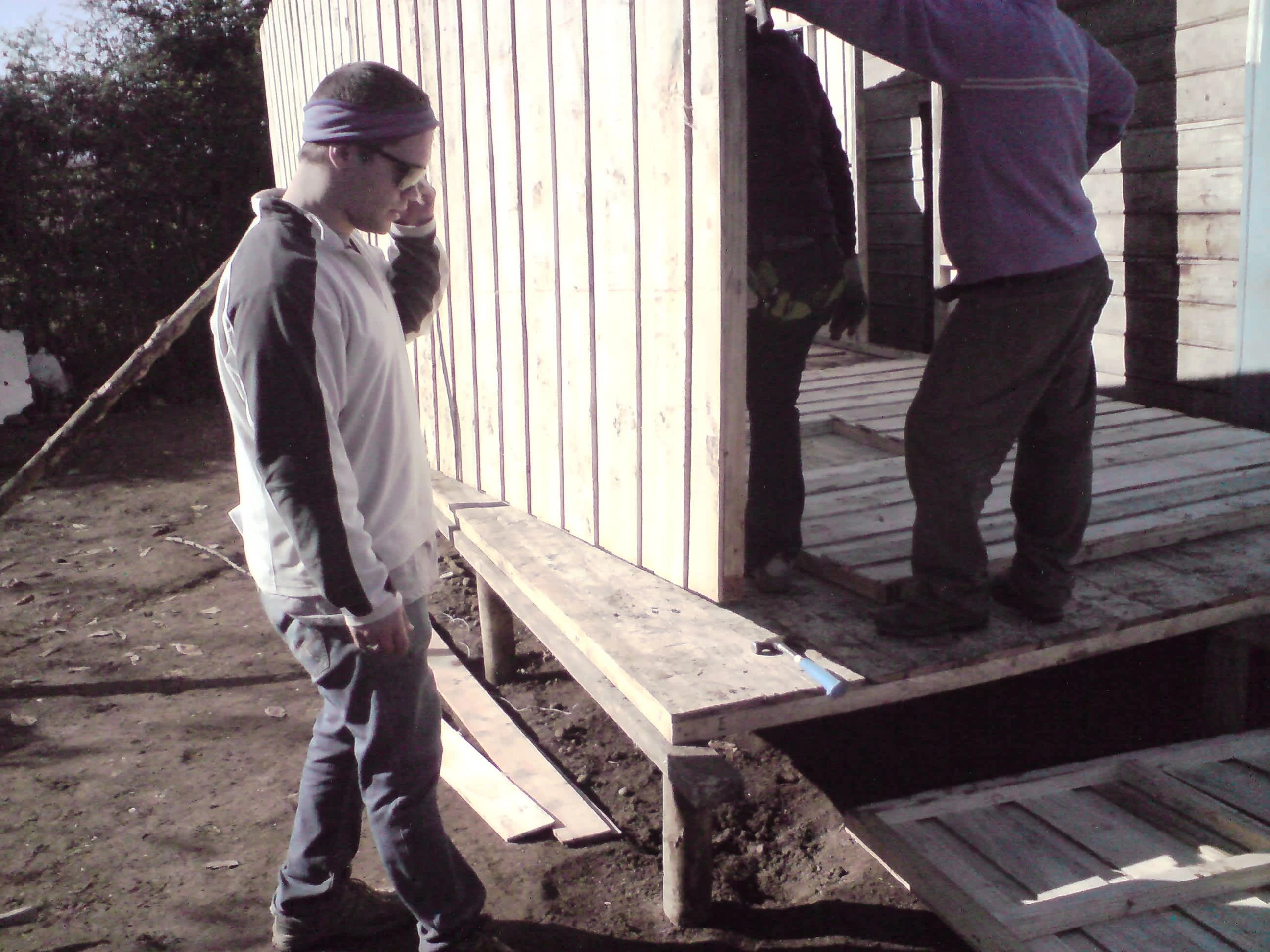
Sometimes you just have to work with what you got. Romeral, May 2010. Photo by Ben Angel
Discussion
The mediagua is a significant contribution to architecture for which Chile can be proud. It is an easy-to-construct emergency shelter requiring 4-5 unskilled builders two days to put together in the field.
There are still numerous flaws in the design, fabrication, and methods of assembling mediaguas here in Chile, some of which have been highlighted in the instructions (with methods recommended for use to get around them). Among the leading flaws observed in the effort to build mediaguas following the February 27, 2010, earthquake have been:
Inefficient use of daylight hours, particularly on the first day (this includes scheduling wake-up to be later than the start of civil twilight in the morning, not bringing teams together until well after sunrise – much less equipping them, and logistical issues for transporting teams to their sites).
Poor materials, sometimes because the materials are donated (market forces generally discourage the donation of high-quality lumber), and sometimes because they are simply poorly made (one would suspect that there are flaws in the instructions for creating front and back panels given the frequency that the panels are provided to the sites far out of their intended specifications, and certainly there is no quality control for panels, other than what the organizers themselves might occasionally provide).
Lack of a culture of safety (reliance on individual “common sense” still prevails over everyone watching out for everyone else on the job site, and in most cases, personal protective equipment or PPE is not provided, nor is its use encouraged by organizers).
Lack of adequate insulation in the design (again, these are considered temporary structures for use in temperate or warmer climate zones).
The solution for most of these flaws seems to point to educating organizers on time management and how to better encourage safety, reviewing the instructions given to fabricators and ensuring that fabrication flaws are corrected in the factory rather than in the field, and providing more resources for PPE (as well as mandating their use in the same way that prohibitions during deployment against alcohol, sexual relations, and drug use were mandated over the June 5-6 weekend).
On the other side of this review of mediagua building, the prefabricated structure is a work of genius. Their use can be imagined in countries where the standard of living is high (the transfer of this technology would be quite useful as a response to a similar future disaster in the US Pacific Northwest, for instance) or low (their use in impoverished nations could likewise be imagined). With the addition of insulation to the design, they could be effectively used in cold regions (such as the seismic areas of the Russian Far East or Alaska). The main limiting factor would seem to be the availability of dimensional lumber and appropriate manufacturing facilities.
At present, the design seems mostly to be used within Latin America, with the “Un Techo Para Mi Pais” NGO system being the main way to export the technology. If successfully used in Latin America, a more global vision should be encouraged, with mediaguas becoming the leading emergency or temporary housing structure worldwide.
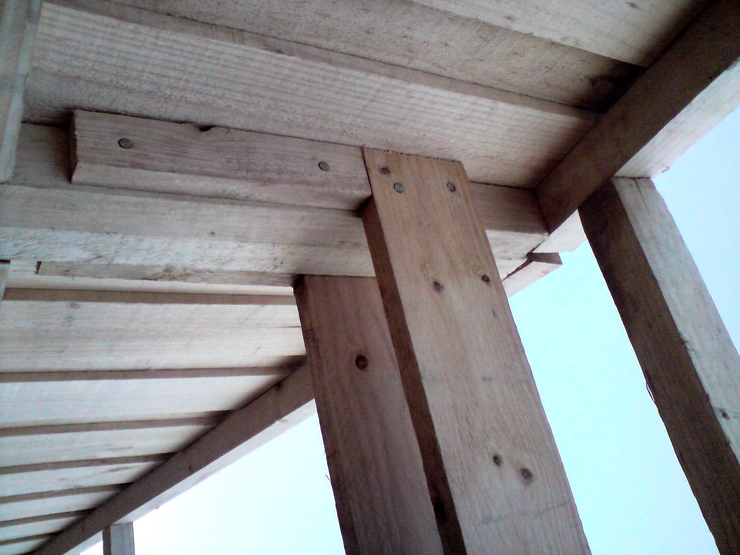
Exempliary main beam construction by Andrew Smith at Los Coipos in April 2010. Photo by Ben Angel.
Acknowledgments
The author of this manual would like to thank the following for their contribution to this work.
The Solidarity Group (led by Natalia Bustos) – for including the author as a team leader in the construction of a mediagua in the village of Los Coipos in late April.
Andrew Smith and Clay Weathers – for their input and instruction on how to build a mediagua, and editorial suggestions.
Julie Redding of Volunteer Horizons – for her input on volunteer safety as well as editorial suggestions.
The organizers at Romeral – for proving the author wrong on just how far a deformed wooden panel can be corrected with enough nails and the proper procedure.
Cristian Tala – for including the author as a team leader at Linares in late May, and for referrals to other volunteer opportunities after his final weekend as an organizer.
Roberto Casarejos CAR, of AFS – for including the author as a team leader at Las Lomas, and for showing great and highly useful attention to details in organizing the construction of mediaguas at that village.
Anghelo Ibacache – for including the author as a volunteer in two June 2010 outings (at Lota and Santiago’s Estacion Central district).
Fellow volunteers the author worked with – for contributing to the author’s understanding of Chile, as well as putting up with all the photos being taken, as well as my lack of ability to speak and understand more than very basic Spanish, and experiments while constructing mediaguas.
Those people receiving the mediaguas the author helped to build – for allowing a foreigner the chance to help out as well as learn more about Chile.
And lastly, “Un Techo Para Chile” – for the opportunity to contribute to the reconstruction of this land, one strangely similar to that part of the United States where the author grew up.
Like this project
Posted Nov 11, 2024
Online English-language instruction on how to build an emergency shelter from kits distributed following the catastrophic Feb. 27, 2010, earthquake in Chile.
Likes
0
Views
17


