SolidWorks Automotive Differential Design Project
Ayomide Olagoroye
SolidWorks Automotive Engineering – Vehicle Differential Assembly
Project Overview
The objective of this project was to design, model, and assemble a highly accurate, manufacturing-ready Vehicle Differential System using SolidWorks. A car differential is a critical mechanical assembly that allows wheels on the same axle to rotate at different speeds, essential for maintaining traction and stability when cornering.
This case study highlights the end-to-end engineering workflow, from initial gear design using advanced parametric equations to full kinematic assembly and interference analysis.
Role: Lead Mechanical Engineer & 3D Product Designer
Software Used: SolidWorks (CAD Modeling, Assembly, Motion Simulation)
Key Focus Areas: Parametric gear design, advanced assembly constraints, GD&T (Geometric Dimensioning and Tolerancing), and manufacturing-ready documentation.
The Challenge
Designing an automotive differential presents several complex engineering hurdles:
Complex Gear Geometry: Generating accurate hypoid or straight bevel gear profiles that match perfectly without mechanical interference.
Load & Torque Management: Designing structural components (housing, bearings, and shafts) capable of handling high torsional loads.
Kinematic Integrity: Ensuring the spider gears, side gears, and ring gear interact dynamically with zero collisions during differential rotation.
Design & Modeling Process
The system was broken down into its core functional components, modeled individually before final integration.
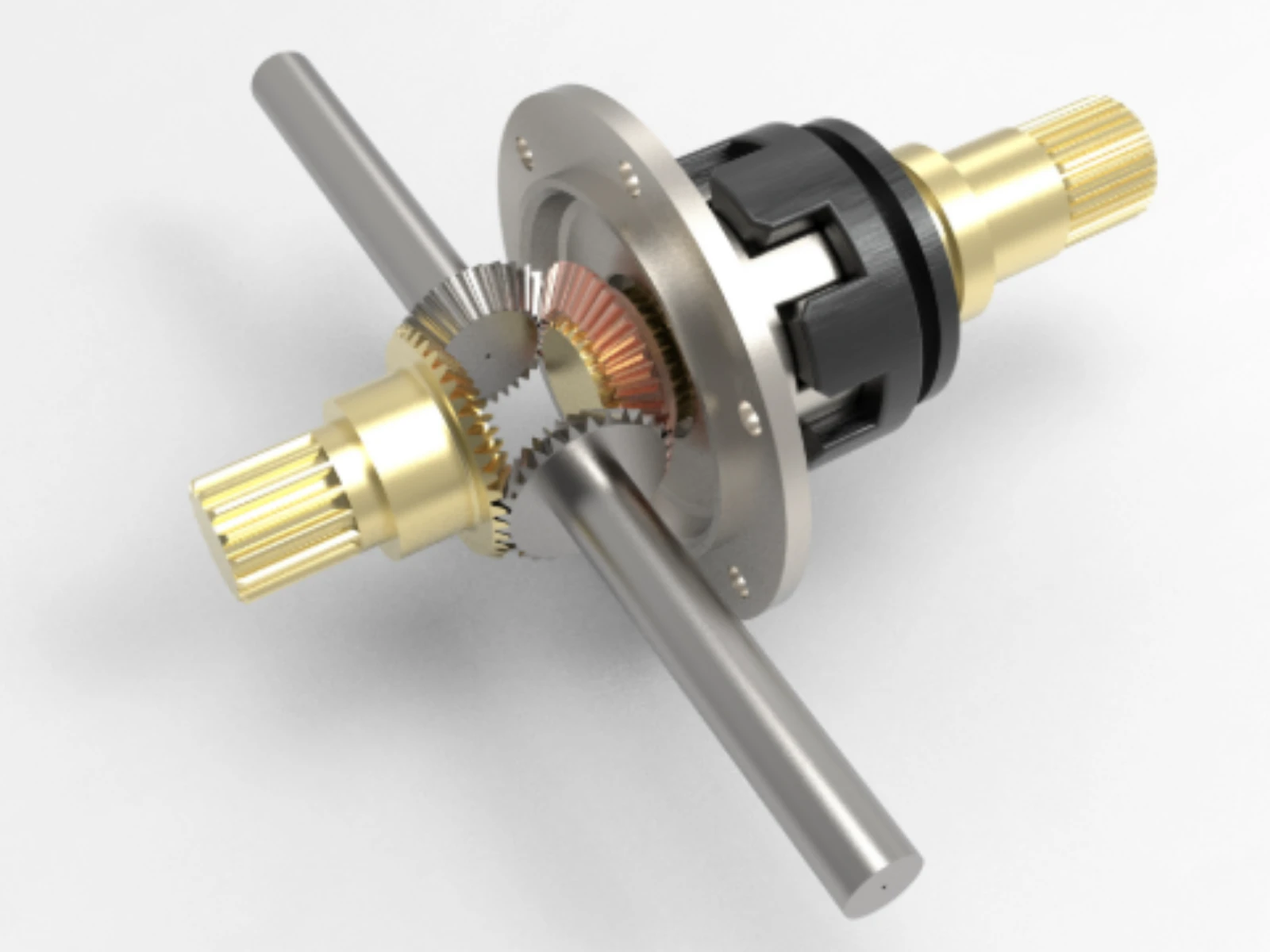
1. Parametric Gear Engineering
The heart of the differential lies in its gear train. To ensure realistic performance and accurate tooth engagement:
Bevel & Ring Gears: Modeled utilizing precise diametral pitch, module, and pressure angles. Parametric equations were used to map out the exact involute curve of the gear teeth.
Backlash Optimization: Integrated a specific backlash tolerance into the gear profiles to allow for lubrication film thickness and thermal expansion during operation.
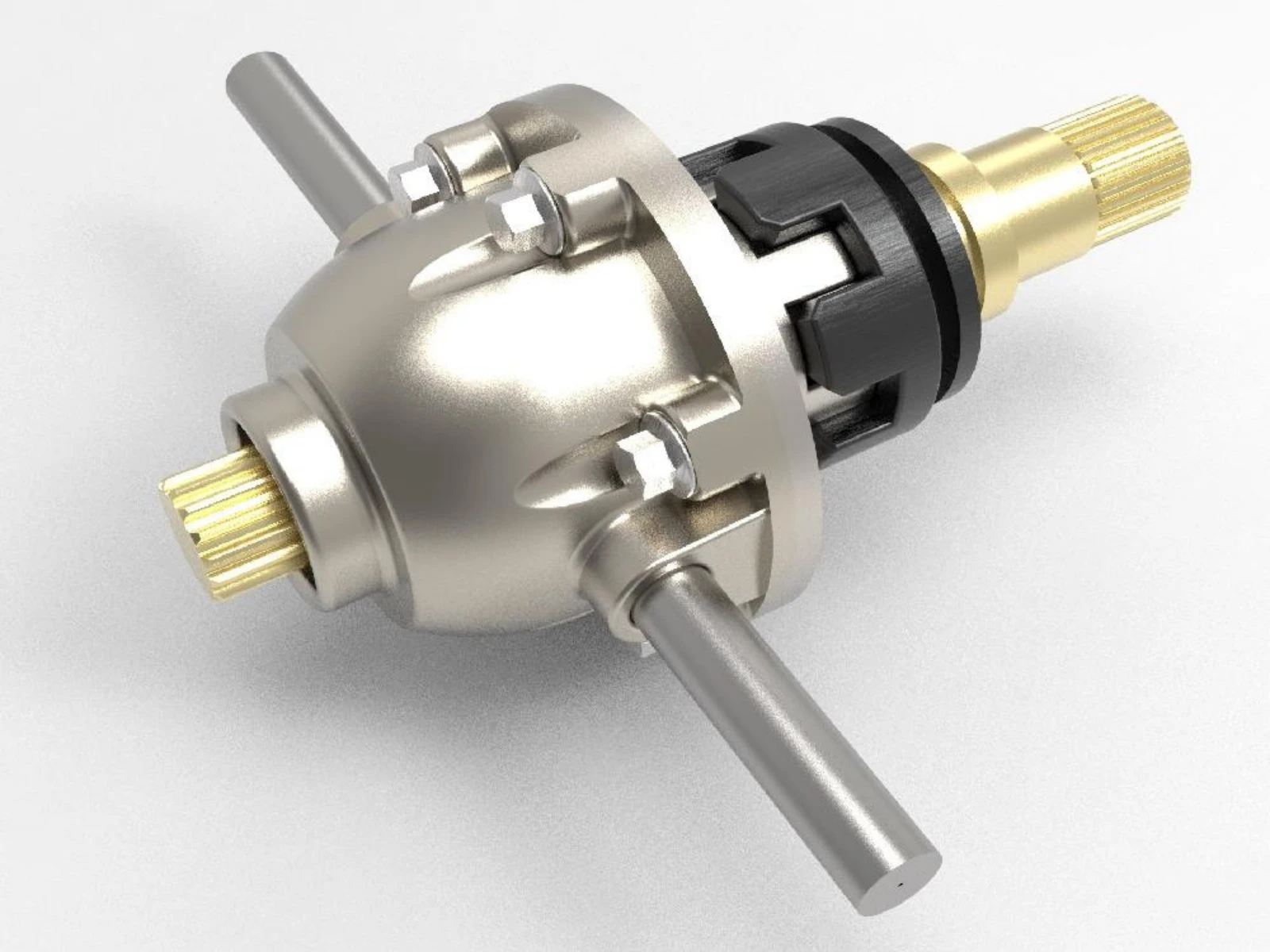
2. Core Structural Components
Differential Housing / Case: Formed using advanced core/cavity design principles, mimicking a cast-iron or forged steel component with appropriate draft angles and filleted corners to minimize stress concentrations.
Input Pinion & Axle Shafts: Engineered to standard automotive spline dimensions to guarantee seamless power transmission from the driveshaft to the wheels.
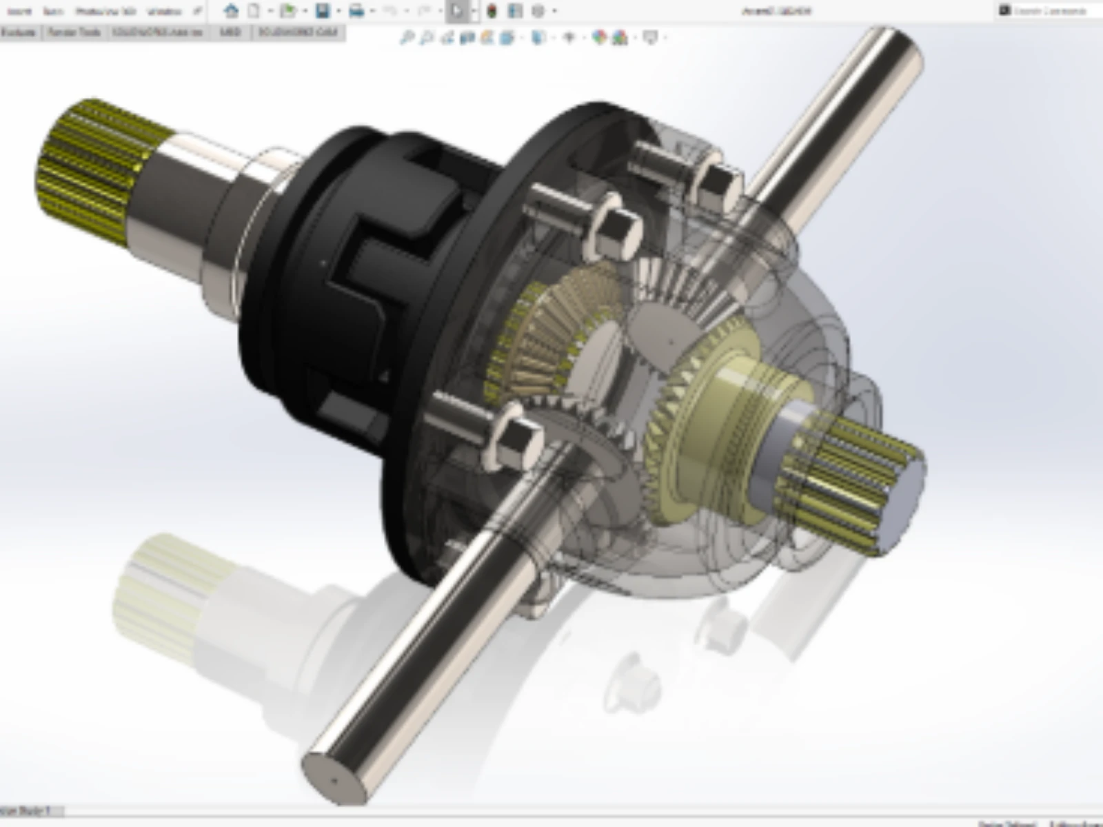
Assembly, Mates, & Kinematic Simulation
Once individual components were validated, they were pulled into a top-down assembly environment.
Mechanical Mates: Specialized Gear Mates were established between the pinion and ring gear, as well as between the inner spider bevel gears and side gears.
Interference Detection: Executed a dynamic static and motion-based interference analysis within SolidWorks. The design passed with zero overlapping geometries, ensuring flawless structural clearance.
Motion Study: Simulated a cornering scenario where the left axle slowed down while the right axle accelerated, proving the mechanical logic of the spider gear cage functioned exactly to real-world specifications.
Manufacturing Readiness & Documentation
A beautiful 3D model is only as good as its execution on the factory floor. The project was completed with industrial viability in mind:
Engineering Specification Note: All internal tolerances were designed to accommodate standard automotive manufacturing processes such as CNC machining, hobbing, and high-pressure casting.
2D Technical Drawings: Formatted full engineering sheets complete with exploded views, Bill of Materials (BOM), and rigorous GD&T callouts for precise bearing alignments.
Material Allocation: Modeled with accurate density metrics (e.g., AISI 8620 alloy steel for case-hardened gears), allowing for exact center-of-mass and total assembly weight calculations.
Final Outcomes
Achieved a fully functional, mathematically accurate CAD asset ideal for finite element analysis (FEA) or downstream high-fidelity rendering.
Optimized assembly workflow, reducing component count where possible to minimize overall rotational inertia.
Created a high-impact engineering portfolio piece that demonstrates mastery of automotive kinematics and complex parametric design.
Like this project
Posted Jul 1, 2026
Designed and assembled a vehicle differential using SolidWorks for manufacturing readiness.