
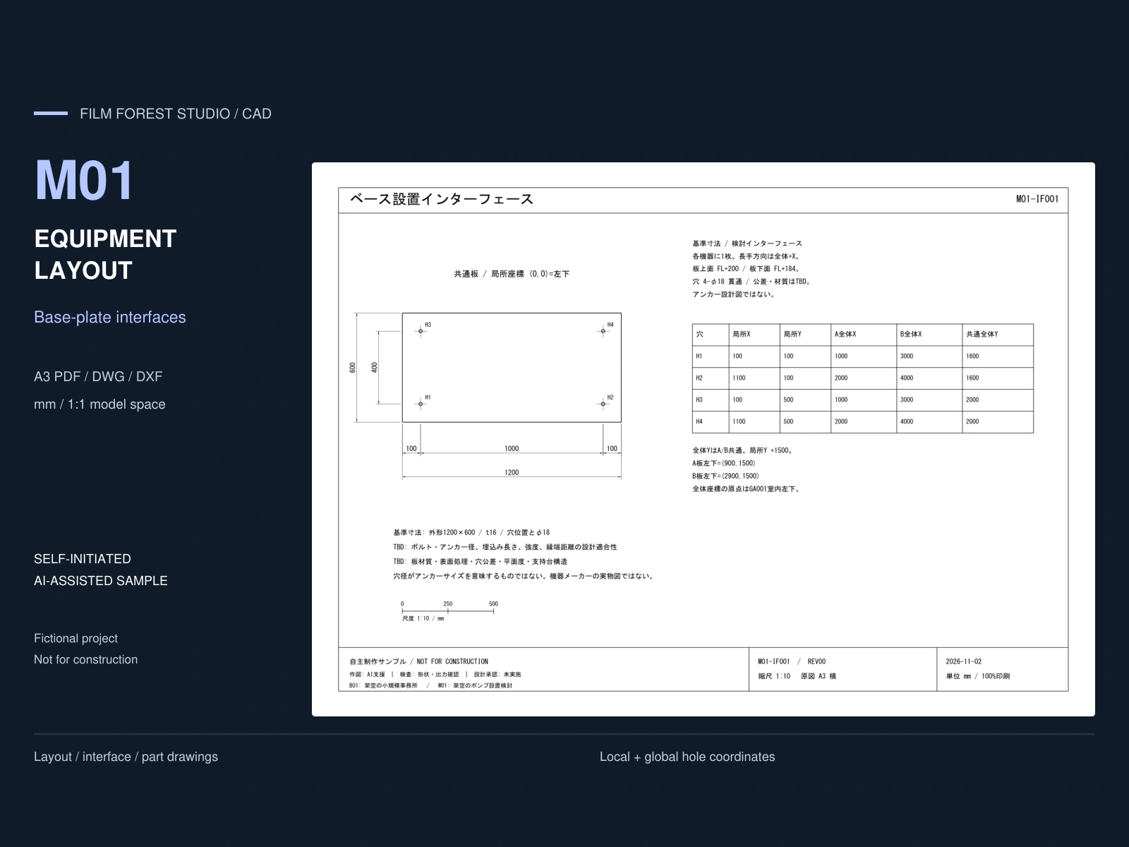
This self-initiated case organizes equipment placement and base-plate interface information into a consistent 2D drawing set. The fictional pump room measures 6,000 x 4,000 mm and contains two equipment outlines.
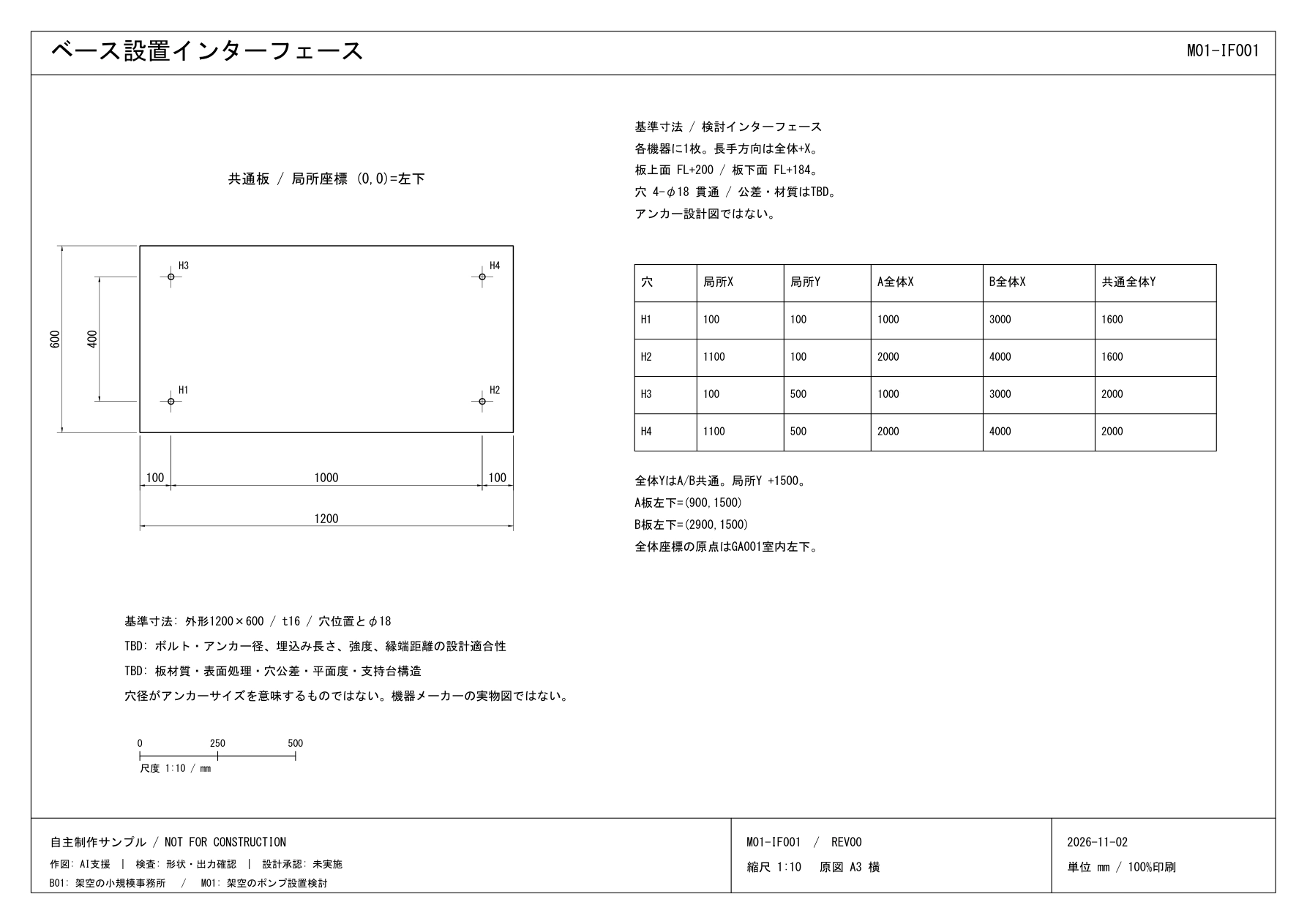
DRAWING SCOPE Equipment layout, front/side views, base interface, part drawing and an item list. A common 1,200 x 600 x 16 mm plate uses four diameter-18 holes. The hole centres are tabulated in both local and global coordinates; a partial section identifies plate thickness and hole diameter. Equipment and part identifiers are consistent across the sheets.
DELIVERABLES Japanese A3 PDF, editable DWG and DXF. Model space uses millimetres at 1:1. Actual AutoCAD Core 2022 save, reopen and PDF output were checked in the source workflow.
MY ROLE & PROVENANCE AI-assisted, self-initiated CAD drafting and documentation sample. This is fictional, not paid client work, a manufacturer-approved drawing, anchor design, fabrication approval or strength calculation. Material, tolerances and surface finish remain marked TBD. Dimension associativity is not guaranteed.
FOR A SIMILAR ASSIGNMENT I can discuss source-based equipment-layout redrawing, interface documentation, dimensional cleanup and PDF/DWG/DXF delivery. The supplied information, responsibilities, compatibility, schedule and fee are agreed before work.
Full drawing pages: https://www.foriio.com/filmforeststudio/wk_AZ0Qy1qzjTPJjRL73QBFaGGDIiFLm1Dq3PnN-wjQNPG6uZBJpQ
0 likes · 1 view · Nov 1, 2026
Fictional equipment layout, base-plate interface and part drawings with local/global hole coordinates. AI-assisted self-initiated CAD sample.
