
Adeagbo AbdulJeleel
Designing PCBs, electronics, embedded and product design


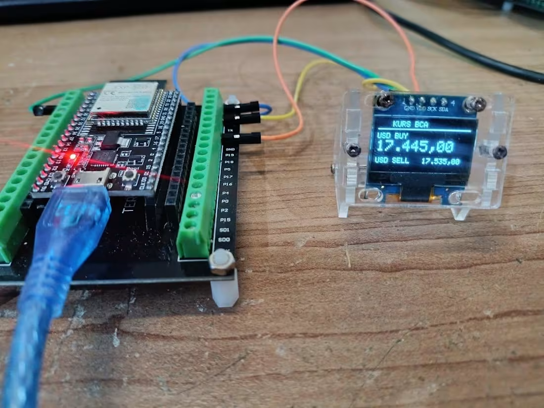
IoT-Based USD to IDR Exchange Rate Display Using Bank BCA Exchange Rates
Real-Time Bank BCA USD/IDR Exchange Rate Monitor using ESP32 and OLED Display with live internet updates.
Features:
• Real-time USD/IDR exchange rate display
• ESP32 WiFi connectivity
• OLED SSD1306 interface
• Automatic online data refresh
• Lightweight and low-power system
• Compact embedded monitoring device
#ESP32 📡 | #IoT 🚀 | #EmbeddedSystems 💻 | #Arduino ⚙️ | #Programming 📚
1
208
Raspberry Pi CM5 Carrier Board with Class-D Amp
In this design, Texas Instruments TPA3118 Class-D amplifier is integrated on the PCB carrying Raspberry Pi CM5. Power supply is coming from USB-PD input via Type-C port.
I/O ports
1 x HDMI
1 x DSI 22p FPC connector
2 x USB 3.0 Type-A
2 x USB 2.0 Type-A
1 x M.2 M-Key PCIe slot for SSD
1 x 3.5mm stereo Line-out jack
1 x USB Type-C Debug/Flash
1 x USB Type-C PD
1 x PWM Fan connector
1 x RGB LED 3-p connector connected to GPIO
1 x rotary encoder input connected to GPIO
ICs
Texas Instruments PCM5102A, 2.1 VRMS, 112/106/100 dB Audio Stereo DAC with PLL and 32-bit, 384 kHz PCM Interface
Texas Instruments TPA3118D2, 30-W stereo, 60-W mono, 4.5- to 26-V supply, analog input Class-D audio amplifier
Injoinic IP2721, TYPEC/PD2.0/PD3.0 Physical Layer IC for USB Type-C input Interfaces
Terminus Tech FE1.1s, USB 2.0 High Speed 4-port Hub Controller
0
83
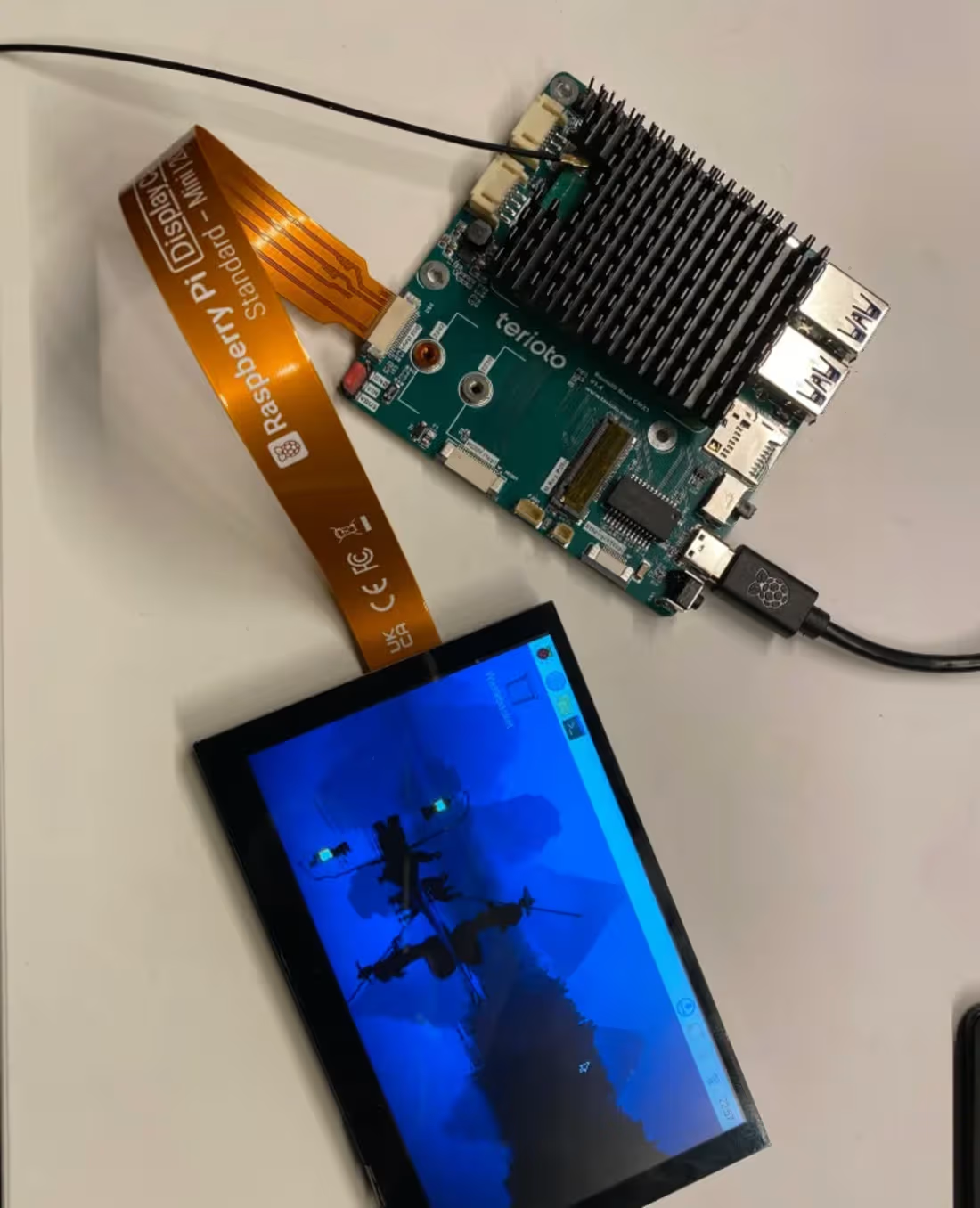
Raspberry Pi CM5 IO Board with USB 2.0 OTG
The official Raspberry Pi Compute Module 5 IO board doesn’t include the USB 2.0 path switch IC, which was in its elder brother CM4 IO board. Also, it uses CM5’s own CC control pins for USB Type C port. To make my design compatible with both CM4 and CM5, I integrated an USB 2.0 switch IC in the similar way, but with a little bit different configuration.
The board need to have 2 x USB 2.0 ports. So I needed to add an USB 2.0 hub IC and an USB path switch chip, similar to the official Raspberry Pi CM4 IO board. But I needed to modify it to use an USB Type-C port and use CC control pins of CM5. The elder CM4 series modules didn’t have CC control pins. Thus, I also added DNP resistors, where I can solder 5.1K resistors for using CM4 on this board.
The official Raspberry CM4 IO board used VBUS to automatically switch the OTG config via USB_OTG_ID pin. But on my design, +5V line may be supplied from external power source. It means I should use 5A rated ideal diode. But the requirements was only using USB 2.0 as normal Host, instead of standard USB OTG compatible port. As we anyway need BOOT button to set the compute module into flashing mode, I decided to use a DPDT slide switch instead of tactile boot button. In this way, I could manage setting BOOT and OTG_ID flags using a single switch sliding.
0
98
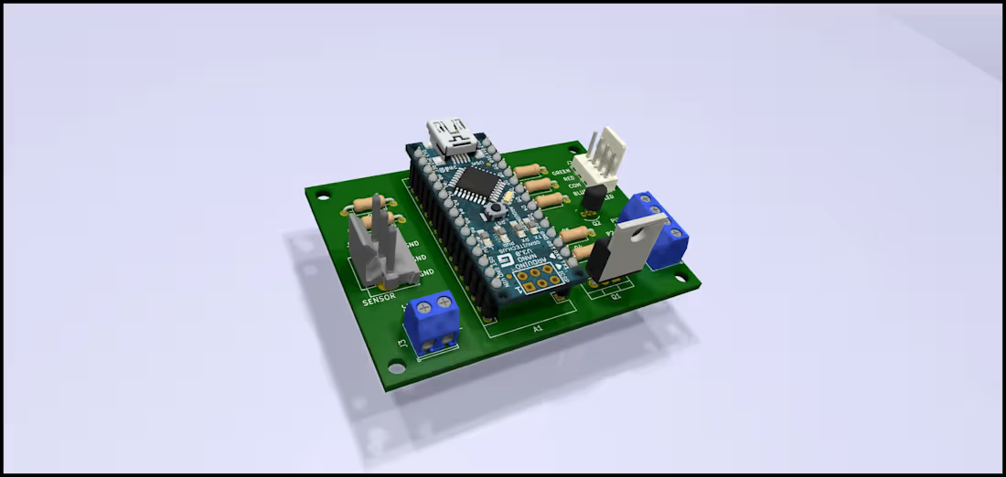
Arduino Nano-Based PCB Design
I designed a custom PCB built around the Arduino Nano, creating a compact hardware platform for integrating the microcontroller with supporting electronic components and external peripherals.
The design involved organizing the Arduino Nano interface, power connections, input/output lines, and supporting circuitry into a clean and practical PCB layout. I focused on efficient component placement, clear signal routing, reliable power distribution, and maintaining a layout that is easy to assemble and integrate into a larger embedded system.
This project strengthened my experience in Arduino-based hardware development, PCB layout, embedded electronics, component integration, and microcontroller interfacing.
0
89