Adjustable Trailing Edge Wing Design
The idea for this design came to me as I was completing my masters thesis. A main requirement for an effective FSAE Aero package is not simply to maximize downforce. True potential lies in Center of pressure balance and understanding its relationship and influence on vehicle dynamics. To achieve an even better level of control, the ability to alter force distribution in relation to the COG is a major advantage.
With an adjustable trailing edge wing design, this potential can be accomplished through the use of an actuator, to control the camber line of the wing.
CONSTRUCTION
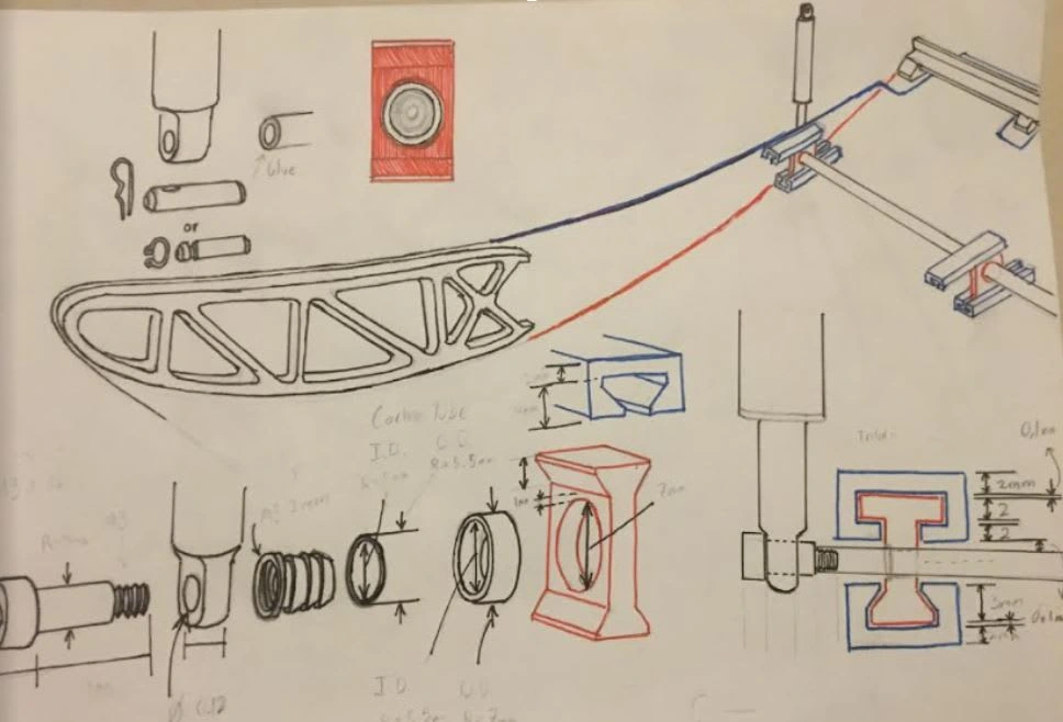
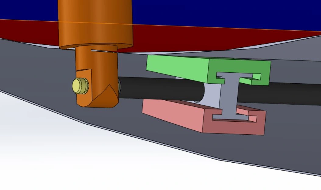
A carbon rod is attached to the actuator and inserted through a slide mount (RED). The rod will extend along the span of the wing. T-Slots (BLUE) are glued to the inside of the wing skin as a guide system. The slide mount is able to translate along the chord length inside the T-Slots.
The Leading edge and center section of the wing skin are glued permanently to the internal wing structure. The rest of the wing skin is supported by the movable system.
KINEMATICS
STEP 1
When the actuator is increased, this wing skins will move downward, allowing for the camber line to be changed. This only possible when the top and bottom sides of the wing skin (RED & BLUE) are free to slide next to each other
STEP 2
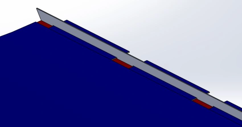
To achieve movement between upper (BLUE) and lower (RED) wing skins, a gurney flap will be attached to the inner side of the lower wing skin (RED) and will include slots. The upper skin (BLUE) will have tabs that correspond to the slots in the lower wing.
As shown in the TOP diagram of the picture below, an excess of upper wing skin will protrude out behind the gurney flap. As the actuator moves the assembly down. the upper wing skin will be allowed to move freely and retract to the front side of the gurney assembly.
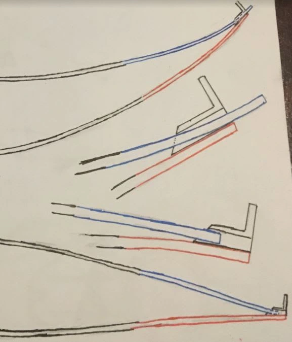
Wing Skin with Gurney Flap Slot Design
CROSS SECTION
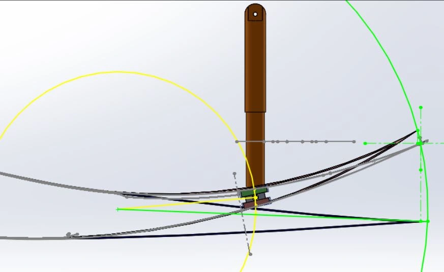
I created the kinematics of the assembly in Solidworks to find the center of rotation. As you can see, only a short change in position of the actuator will result in a relatively large change in trailing edge position and therefore camber line.
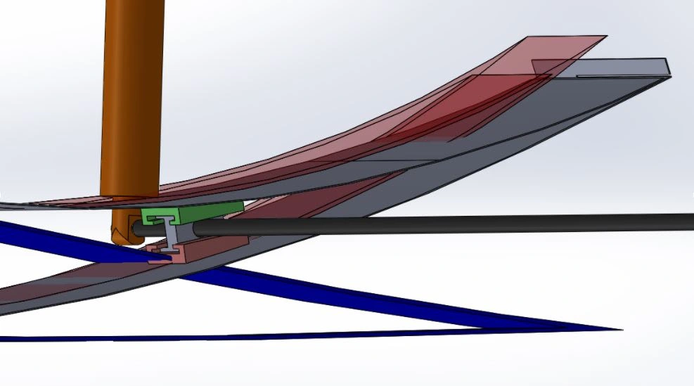
3D Model
The assembly consists of the
Actuator (ORANGE)
Wing with gurney flap in standard position (GRAY)
Increased camber line position (RED)
Decreased camber line position (BLUE)
Carbon support rod (BLACK)
Upper T-Slot (GREEN)
Lower T-Slot (RED)
Slide mount (GRAY)
Slot System Close up
Like this project
Posted Jan 15, 2022
Likes
0
Views
8


