
Ship Hull Lines Plan & 3D Modelling
Project Overview
This project showcases the development of ship hull geometry through an integrated 2D and 3D CAD design workflow.
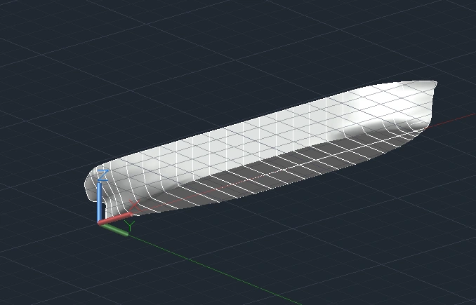
The work combines a detailed Lines Plan with a corresponding 3D Hull Model, providing a coordinated representation of the vessel's hull form for naval architecture and marine design applications.
Project Objective
The objective was to develop a clear and consistent representation of the vessel's hull geometry, connecting traditional naval architecture drawings with three-dimensional hull modelling.
Design Process
1. Hull Lines Plan Development
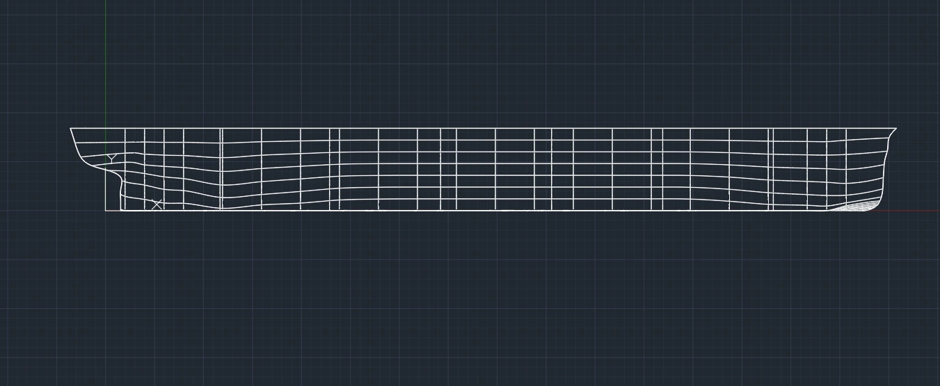
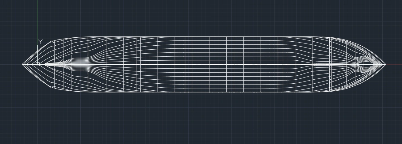
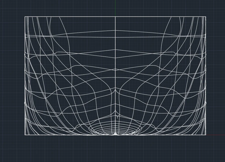
Preparation of the principal hull geometry drawings, including:
Profile Plan (Sheer Plan)
Body Plan
Half-Breadth Plan
Stations and transverse sections
Waterlines and buttock lines
2. 3D Hull Modelling
Development of the corresponding three-dimensional hull form, representing the vessel's external geometry and surface arrangement.
3. 2D and 3D Geometry Coordinates
Organization of the 2D drawings and 3D model to provide a consistent representation of the hull form for design visualization and further engineering development.
Project Deliverables
Ship Lines Plan
Profile, Body, and Half-Breadth views
3D Hull Model
Hull Geometry Visualizations
CAD Drawings for Naval Architecture Applications
Final Outcome
The project demonstrates an integrated approach to hull geometry development, combining traditional 2D ship design documentation with modern 3D CAD modelling.
The resulting drawings and model provide a useful geometric foundation for design review and potential subsequent naval architecture and structural engineering work.
0 likes · 0 views · Nov 2, 2026
Ship Hull Lines Plan & 3D Modelling Project Overview This project showcases the development of ship hull geometry through an integrated 2D and 3D CAD design ...
