PCB Electronics Enclosure Design & Mechanical CAD Development
Portfolio project

Project Overview
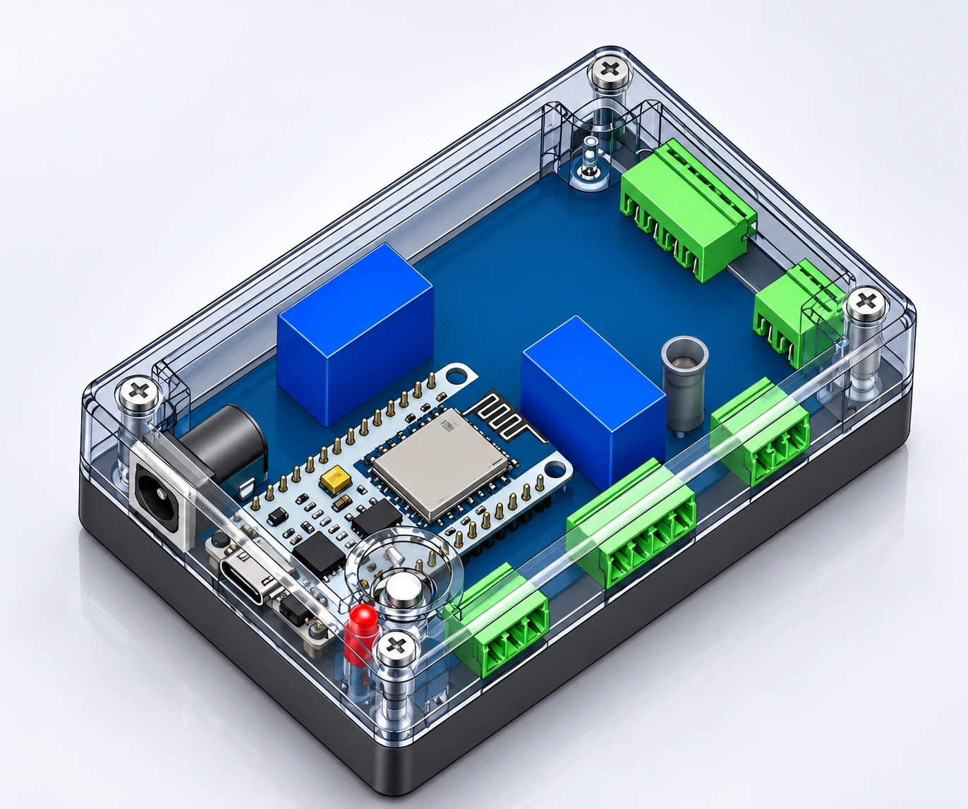
This project focused on developing a compact electronics enclosure designed to accommodate a PCB assembly and its internal components while maintaining a practical, organized housing structure.
The design combines a protective outer enclosure, PCB mounting points, internal component clearance, ventilation features, connector openings, and a removable top cover.
The goal was to create a clear mechanical design that brings the electronic components and enclosure together in a structured 3D CAD assembly.
The Design Challenge
The enclosure needed to accommodate multiple electronic components within a compact footprint while allowing access to external connections and maintaining a clean housing layout.
Key design considerations included:
PCB positioning and mounting support
Internal component placement and clearance
Enclosure dimensions and overall proportions
Ventilation openings and connector access
Screw locations and housing assembly
Top cover and bottom housing integration
My Design Approach
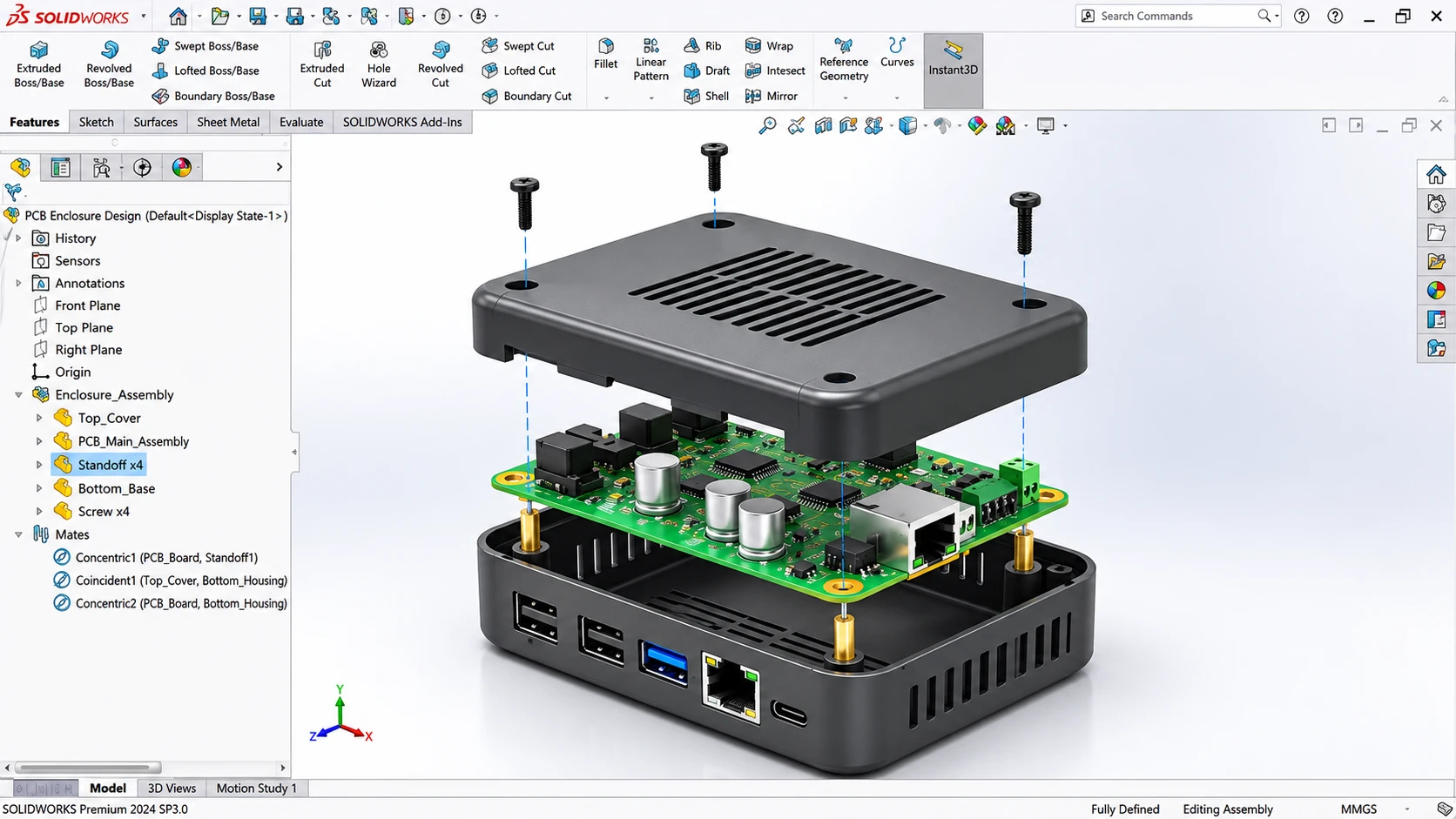
I developed the enclosure using SolidWorks, focusing on the relationship between the PCB, internal components, mounting features, and external housing.
The work included:
1. 3D CAD Enclosure Design
Development of the top cover and bottom housing with attention to the overall shape, enclosure proportions, mounting locations, and external openings.
2. PCB Integration & Component Layout
Positioning the PCB within the enclosure and arranging the internal components to demonstrate their fit and relationship with the housing.
3. Mechanical Assembly
Creating an assembled CAD model showing the relationship between the enclosure, PCB, standoffs, mounting hardware, and cover.
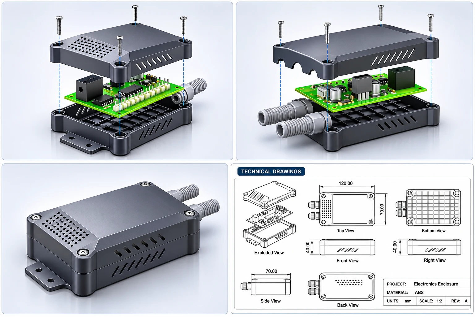
4. Exploded Assembly Views
Preparing exploded visualizations to communicate how the individual enclosure components fit together and how the assembly is organized.
5. Technical Drawings & Design Documentation
Creating supporting CAD views, including orthographic views, dimensions, section details, and assembly references.
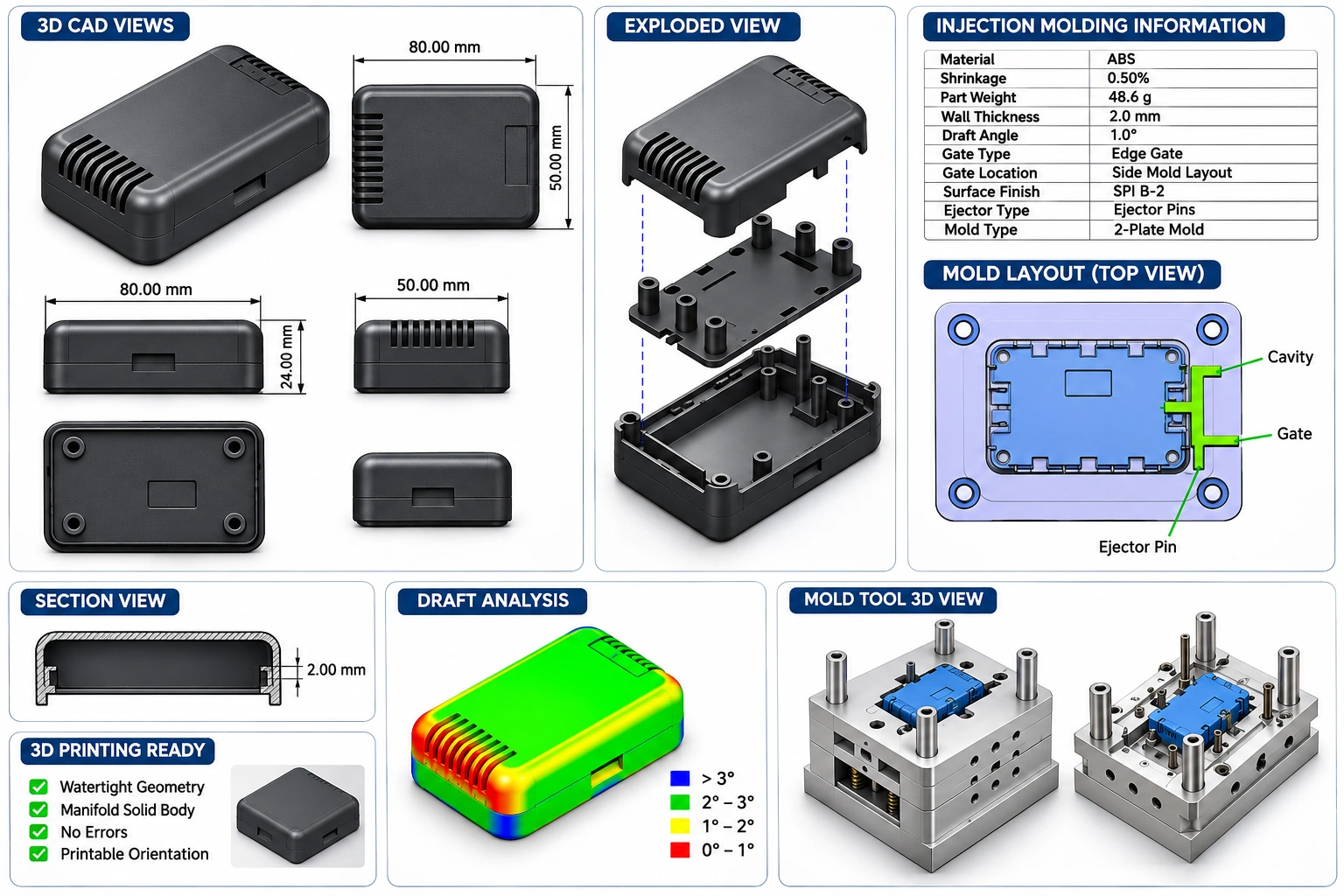
6. Design for Manufacturing Considerations
Reviewing enclosure features such as wall thickness, mounting points, ventilation, draft angles, and part geometry with injection molding and 3D printing considerations in mind.
Project Deliverables
3D CAD enclosure model
PCB integration and component layout
Mechanical CAD assembly
Exploded assembly views
Enclosure design and technical drawings
Sectional and orthographic views
Product visualization renders
Manufacturing-oriented design references
Tools Used
SolidWorks
3D CAD Modeling
Mechanical Assembly Design
Technical Drawing
Project Outcome
The project produced a detailed 3D CAD representation of an electronics enclosure, showing how the PCB and internal components are organized within the housing.
The resulting design documentation communicates the enclosure structure, component arrangement, assembly relationships, and key mechanical features for further prototype development and manufacturing review.
Need an electronics enclosure, PCB housing, or custom mechanical CAD design? I can help develop your product from concept and component layout through 3D CAD modeling and technical documentation.
0 likes · 7 views · Nov 1, 2026
Developed a compact electronics enclosure using SolidWorks.


